REAR DRIVE SHAFT ASSEMBLY (for AWD) REASSEMBLY

-
INSTALL REAR DRIVE SHAFT DUST COVER
-
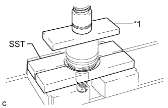
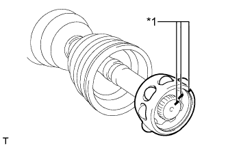
Text in Illustration *1 Steel plate Using SST and a steel plate, install a new rear drive shaft dust cover to the rear drive shaft inboard joint assembly.
- SST
- 09527-21011
Note
-
The rear drive shaft dust cover should be completely installed.
-
Be careful not to damage the rear drive shaft dust cover.
-
-
INSTALL REAR DRIVE SHAFT OUTBOARD JOINT BOOT
-
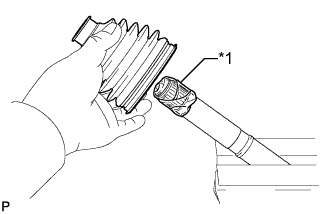
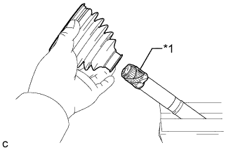
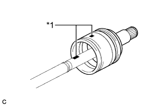
Text in Illustration *1 Vinyl tape Wrap the spline of the drive shaft with vinyl tape to prevent the boot from being damaged.
-
Install new parts to the outboard joint shaft in the following order:
-
Rear drive shaft outboard joint boot clamp
-
Rear drive shaft outboard joint boot
-
No. 2 rear drive shaft outboard joint boot clamp
-
-
Pack the rear drive outboard joint shaft assembly and rear drive shaft outboard joint boot with grease from the boot kit.
Grease capacity 50 to 70 g (1.8 to 2.5 oz.)
-
-
INSTALL REAR DRIVE SHAFT OUTBOARD JOINT BOOT CLAMP
-
Hold the rear drive shaft assembly lightly in a vise between aluminum plates.
Note
Do not overtighten the vise.
-
Secure the rear drive shaft outboard joint boot clamp onto the boot.
-
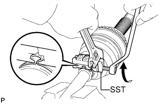
Place SST onto the rear drive shaft outboard joint boot clamp.
- SST
- 09521-24010
-
Tighten the SST so that the rear drive shaft outboard joint boot clamp is pinched.
Note
Do not overtighten SST.
-
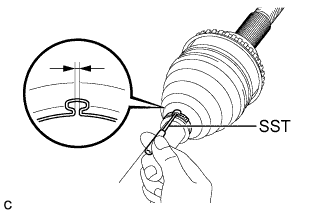
Using SST, inspect the clearance of the rear drive shaft outboard joint boot clamp.
- SST
- 09240-00020
Clearance 1.2 to 4.0 mm (0.0472 to 0.157 in.) Note
If the measured value exceeds the specified value, retighten the clamp.
-
-
INSTALL NO. 2 REAR DRIVE SHAFT OUTBOARD JOINT BOOT CLAMP
-
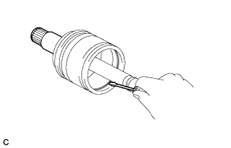
Using a screwdriver, install a new No. 2 rear drive shaft outboard joint clamp as shown in the illustration.
Note
Do not damage the outboard joint boot.
-
-
INSTALL REAR DRIVE SHAFT INBOARD JOINT ASSEMBLY
-
Text in Illustration *1 Vinyl tape Wrap the spline of the outboard joint shaft with vinyl tape to prevent the boot from being damaged.
-
Install new parts to the outboard joint shaft in the following order:
-
No. 2 rear drive shaft inboard joint boot clamp
-
Rear drive shaft inboard joint boot
-
Rear drive shaft inboard joint boot clamp
-
-
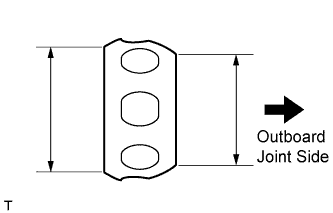
Install the ball cage to the outboard joint shaft.
Note
Install the ball cage with its smaller inner diameter side facing the outboard joint.
-
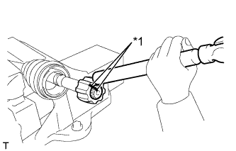
Text in Illustration *1 Matchmark Align the matchmarks placed before removal and install the inner race to the rear drive outboard joint shaft assembly using a brass bar and a hammer.
Note
Be careful not to damage the inner race.
-
Using a snap ring expander, install a new shaft snap ring.
-
Text in Illustration *1 Matchmark Align the matchmarks placed before removal and install the cage to the inner race.
-
Install the 8 balls with grease to the inner race.
Note
Be careful not to drop the balls.
Tech Tips
Apply grease onto the balls to keep them from falling.
-
Pack the inboard joint shaft and boot with grease.
Grease capacity 85 to 105 g (3.0 to 3.7 oz.) -
Text in Illustration *1 Matchmark Align the matchmarks and install the rear drive shaft inboard joint assembly to the rear drive shaft outboard joint shaft assembly.
-
Using a screwdriver, install the drive shaft snap ring to the rear drive shaft inboard joint assembly.
-
-
INSTALL REAR DRIVE SHAFT INBOARD JOINT BOOT
-
Install the rear drive shaft inboard joint boot to the outboard joint shaft.
-
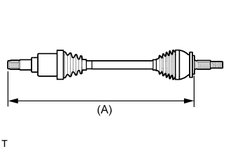
Check whether the drive shaft dimensions are within the following specifications.
Tech Tips
The following table shows the dimension (A) of the drive shaft.
Dimension (A) LH 762.1 to 772.1 mm (2.50 to 2.53 ft.) RH 742.1 to 752.1 mm (2.43 to 2.47 ft.)
-
-
INSTALL NO. 2 REAR DRIVE SHAFT INBOARD JOINT BOOT CLAMP
-
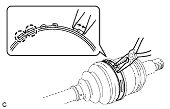
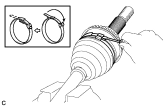
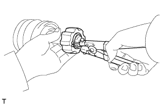
Using needle-nose pliers, engage the 2 claws to install a new No. 2 rear drive shaft inboard joint clamp as shown in the illustration.
-
-
INSTALL REAR DRIVE SHAFT INBOARD JOINT BOOT CLAMP
Tech Tips
Perform the same procedure as for the No. 2 rear drive shaft inboard joint boot clamp.
-
INSTALL REAR DRIVE SHAFT SNAP RING
-
Install a new rear drive shaft snap ring.
-
-
INSPECT REAR DRIVE SHAFT ASSEMBLY
-
Check whether the drive shaft dimensions are within the following specifications.
Tech Tips
The following table shows the dimension (A) of the drive shaft.
Dimension (A) LH 762.1 to 772.1 mm (2.50 to 2.53 ft.) RH 742.1 to 752.1 mm (2.43 to 2.47 ft.) -
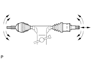
Check that there is no remarkable play in the radial direction of the outboard joint.
-
Check that the inboard joint slides smoothly in the thrust direction.
-
Check that there is no remarkable play in the radial direction of the inboard joint.
-
Check the boots for damage.
-