TRANSFER ASSEMBLY REASSEMBLY

-
INSTALL TRANSFER DRIVEN PINION REAR BEARING
-
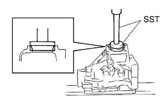
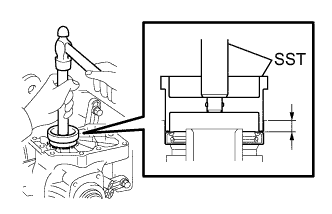
Using SST and a press, press the transfer driven pinion rear bearing (outer race) into the transfer case.
- SST
- 09950-60010 ( 09951-00620 )
- 09950-70010 ( 09951-07150 )
Note
Keep the transfer case horizontal using wooden blocks, etc.
-
Apply gear oil to the transfer driven pinion rear bearing (outer race).
-
-
INSTALL TRANSFER OUTPUT SHAFT WASHER
-
Install the transfer output shaft washer to the transfer case.
Tech Tips
Install the same transfer output shaft washer as the one removed.
-
Apply gear oil to the transfer output shaft washer.
-
-
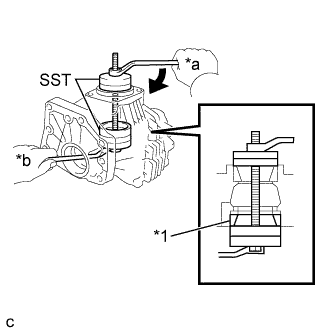
INSTALL TRANSFER DRIVEN PINION FRONT BEARING
-
Apply gear oil to the inner surface of the transfer case.
-
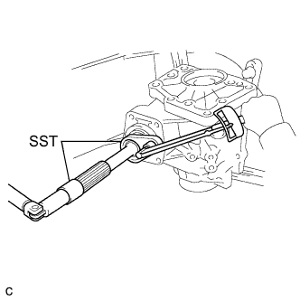
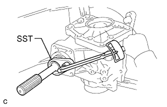
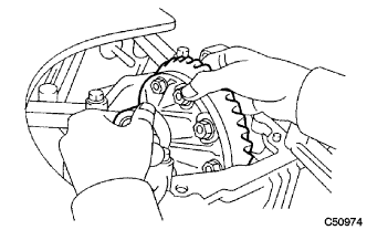
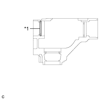
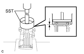
Using SST, install the transfer driven pinion front bearing (outer race) to the transfer case.
- SST
- 09950-60010 ( 09951-00610, 09951-00620, 09951-00650 )
- 09950-60020 ( 09951-00680 )
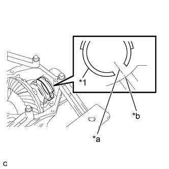
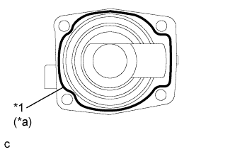
Text in Illustration *1 Transfer Driven Pinion Front Bearing (Outer Race) *a Turn *b Hold -
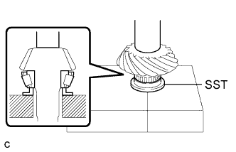
Using SST and a press, press the transfer driven pinion front bearing (inner race) into the driven pinion.
- SST
- 09506-30012
-
-
INSTALL DRIVEN PINION
-
Install the driven pinion to the transfer case.
-
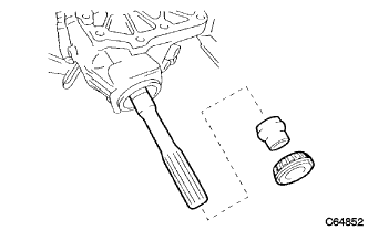
Install a new transfer pinion bearing spacer and the transfer driven pinion rear bearing (inner race) to the driven pinion.
Tech Tips
Install the transfer pinion bearing spacer with the larger inner diameter facing forward as shown in the illustration.
-
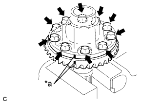
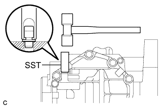
Using SST, install a new gear nut.
- SST
- 09326-20011
- 09556-16030
- Torque:
- without SST
- 270 to 420 N*m { 2753 to 4283 kgf*cm, 199 to 310 ft.*lbf }
- with SST
- 254 to 396 N*m { 2590 to 4038 kgf*cm, 187 to 292 ft.*lbf }
Tech Tips
Use a torque wrench with a fulcrum length of 840 mm (2.76 ft.).
Note
Do not stake the gear nut until the final preload, tooth contact and backlash adjustments are completed.
-
-
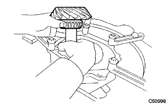
ADJUST DRIVEN PINION PRELOAD
-
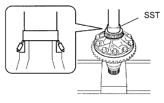
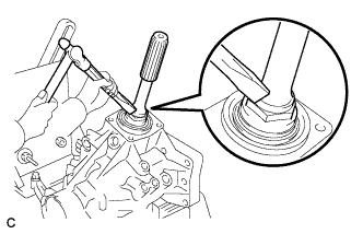
Using SST and a torque wrench, measure the driven pinion preload.
- SST
- 09326-20011
Preload (at Starting) Item Preload New bearing (without SST) 0.68 to 1.13 N*m (7 to 11 kgf*cm, 6 to 10 in.*lbf) New bearing (with SST) 0.49 to 0.81 N*m (5 to 8 kgf*cm, 5 to 7 in.*lbf) Reused bearing (without SST) 0.56 to 0.94 N*m (6 to 9 kgf*cm, 5 to 8 in.*lbf) Reused bearing (with SST) 0.40 to 0.67 N*m (4 to 6 kgf*cm, 4 to 5 in.*lbf) Tech Tips
-
Use a torque wrench with a fulcrum length of 130 mm (5.12 in.).
-
If the preload is more than the specification, replace the transfer pinion bearing spacer with a new one.
-
If the preload is not sufficient, adjust the driven pinion by tightening the gear nut 5° to 10° and measuring the preload until the preload is within the specification.
-
Even if the tightening torque of the gear nut exceeds the specified torque, if the preload is insufficient, loosen the gear nut once and apply rust preventive oil or hypoid gear oil to the gear nut and to the screw or bearing surface of the driven pinion. Then perform the procedure again. If the tightening torque is less than the specified torque, replace the transfer pinion bearing spacer with a new one and adjust it.
-
Do not loosen the gear nut to reduce the preload.
-
-
INSTALL RING GEAR
-
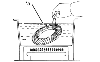
Text in Illustration *a Boiling Water Clean the contact surfaces of the ring gear and transfer ring gear mounting case.
-
Heat the ring gear in boiling water.
-
Carefully remove the ring gear from the boiling water.
-
Align the matchmarks and quickly install the ring gear to the transfer ring gear mounting case.
-
for Seal Lock Bolt:
-
Apply adhesive to whole threads and seat sections of 10 new bolts.
Adhesive Toyota Genuine Adhesive 1324, Three Bond 1324 or equivalent
-
-
Text in Illustration *a Matchmark After the moisture on the ring gear has completely evaporated, install the 10 bolts.
- Torque:
- for Seal Lock Bolt
- 112 N*m { 1142 kgf*cm, 83 ft.*lbf }
- except Seal Lock Bolt
- 78 N*m { 795 kgf*cm, 58 ft.*lbf }
Note
-
Tighten the bolts evenly in a diagonal pattern using several steps.
-
Tighten the bolts after the ring gear has cooled down sufficiently.
-
Confirm whether the bolts are precoated (for Seal Lock Bolt) or uncoated (except Seal Lock Bolt) as the tightening torque is different for each type.
-
In order to ensure proper sealing of the bolts, apply adhesive to the bolts and install them within 10 minutes of adhesive application.
-
-
INSTALL RING GEAR MOUNTING CASE BEARING
-
Using SST and a press, press the ring gear mounting case bearing (inner race) into the transfer ring gear mounting case.
- SST
- 09950-60010 ( 09951-00420 )
-
Install the ring gear mounting case bearing (outer race) to the transfer ring gear mounting case.
-
Apply gear oil to the ring gear mounting case bearing.
-
Using SST and a press, press the ring gear mounting case bearing (inner race) into the transfer ring gear mounting case.
- SST
- 09223-00010
- 09726-40010
-
Install the ring gear mounting case plate washer to the transfer case.
Tech Tips
If replacing the ring gear mounting case plate washer, use one with the same thickness as the one removed.
-
Using SST and a press, press the ring gear mounting case bearing (outer race) into the transfer case.
- SST
- 09950-60010 ( 09951-00620 )
- 09950-70010 ( 09951-07200 )
-
Apply gear oil to the ring gear mounting case bearing.
-
-
INSTALL TRANSFER RING GEAR MOUNTING CASE
-
Apply gear oil to the transfer ring gear mounting case.
-
Install the transfer ring gear mounting case to the transfer case.
-
-
INSTALL NO. 1 TRANSFER OUTPUT SHAFT SPACER
-
Text in Illustration *1 No. 1 Transfer Output Shaft Spacer *a Cutout *b Case Hole Align the cutout on the No. 1 transfer output shaft spacer with the transfer case hole to install it as shown in the illustration.
-
-
INSTALL NO. 2 TRANSFER RING GEAR MOUNTING CASE WASHER
-
Using a brass bar and a hammer, install the No. 2 transfer ring gear mounting case washer.
Tech Tips
If replacing the No. 2 transfer ring gear mounting case washer, use one with the same thickness as the one removed.
-
-
INSTALL BEARING CAP
-
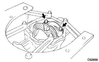
Install the bearing cap with the 2 bolts.
- Torque:
- 63 N*m { 644 kgf*cm, 47 ft.*lbf }
-
-
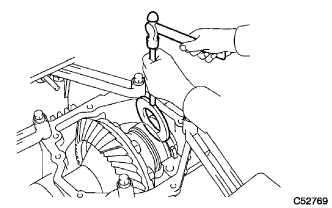
INSPECT RING GEAR BACKLASH
-
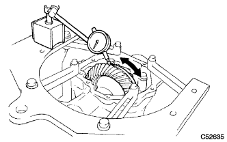
Set a dial indicator perpendicular to a ring gear tooth tip. Secure the driven pinion in place and move the ring gear back and forth to measure the backlash.
Backlash 0.14 to 0.25 mm (0.00551 to 0.00984 in.) Note
Check at least 3 positions on the circumference of the ring gear.
-
Text in Illustration *1 Ring Gear Mounting Case Plate Washer If the backlash is outside the specified range, select a ring gear mounting case plate washer from the table and install it to meet the specified range.
Washer Thickness Mark Thickness mm (in.) Mark Thickness mm (in.) 5Q 1.95 (0.0768) 7N 2.67 (0.1051) 5R 1.97 (0.0776) 7P 2.69 (0.1059) 5S 1.99 (0.0783) 7Q 2.71 (0.1067) 5T 2.01 (0.0791) 7R 2.73 (0.1075) 5U 2.03 (0.0799) 7S 2.75 (0.1083) 5V 2.05 (0.0807) 7T 2.77 (0.1091) 5W 2.07 (0.0815) 7U 2.79 (0.1098) 5X 2.09 (0.0823) 7V 2.81 (0.1106) 5Y 2.11 (0.0831) 7W 2.83 (0.1114) 5Z 2.13 (0.0839) 7X 2.85 (0.1122) 6F 2.15 (0.0846) 7Y 2.87 (0.1130) 6G 2.17 (0.0854) 7Z 2.89 (0.1138) 6H 2.19 (0.0862) 8F 2.91 (0.1146) 6J 2.21 (0.0870) 8G 2.93 (0.1154) 6K 2.23 (0.0878) 8H 2.95 (0.1161) 6L 2.25 (0.0886) 8J 2.97 (0.1169) 6M 2.27 (0.0894) 8K 2.99 (0.1177) 6N 2.29 (0.0902) 8L 3.01 (0.1185) 6P 2.31 (0.0909) 8M 3.03 (0.1193) 6Q 2.33 (0.0917) 8N 3.05 (0.1201) 6R 2.35 (0.0925) 8P 3.07 (0.1209) 6S 2.37 (0.0933) 8Q 3.09 (0.1217) 6T 2.39 (0.0941) 8R 3.11 (0.1224) 6U 2.41 (0.0949) 8S 3.13 (0.1232) 6V 2.43 (0.0957) 8T 3.15 (0.1240) 6W 2.45 (0.0965) 8U 3.17 (0.1248) 6X 2.47 (0.0972) 8V 3.19 (0.1256) 6Y 2.49 (0.0980) 8W 3.21 (0.1264) 6Z 2.51 (0.0988) 8X 3.23 (0.1272) 7F 2.53 (0.0996) 8Y 3.25 (0.1280) 7G 2.55 (0.1004) 8Z 3.27 (0.1287) 7H 2.57 (0.1012) 9D 3.29 (0.1295) 7J 2.59 (0.1020) 9E 3.31 (0.1303) 7K 2.61 (0.1028) 9F 3.33 (0.1311) 7L 2.63 (0.1035) 9G 3.35 (0.1319) 7M 2.65 (0.1043) 9H 3.37 (0.1327)
-
-
INSPECT TOOTH CONTACT BETWEEN RING GEAR AND DRIVEN PINION
-
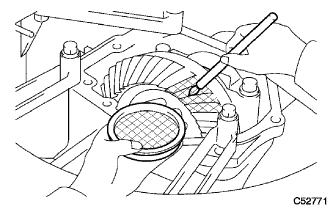
Coat 3 or 4 teeth at 4 different positions on the ring gear with Prussian blue.
-
Turn the driven pinion to rotate the ring gear 10 times or more clockwise and 10 times or more counterclockwise.
-
Rotate the ring gear to inspect the tooth contact pattern.
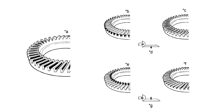
Text in Illustration *a Proper Contact *b Heel Contact *c Face Contact *d Select a washer that will bring the driven pinion closer to the ring gear *e Toe Contact *f Flank Contact *g Select a washer that will shift the driven pinion away from the ring gear - - -
Text in Illustration *1 Transfer Output Shaft Washer If the tooth contact pattern is not correct, select a new transfer output shaft washer that is thicker or thinner as necessary and recheck.
Washer Thickness Mark Thickness mm (in.) Mark Thickness mm (in.) ZA 2.00 (0.0787) KB 2.38 (0.0937) ZB 2.02 (0.0795) LA 2.40 (0.0945) ZC 2.04 (0.0803) LC 2.42 (0.0953) ZD 2.06 (0.0811) MB 2.44 (0.0961) ZE 2.08 (0.0819) NA 2.46 (0.0969) AA 2.10 (0.0827) NC 2.48 (0.0976) AC 2.12 (0.0835) PB 2.50 (0.0984) BB 2.14 (0.0843) QA 2.52 (0.0992) CA 2.16 (0.0850) QC 2.54 (0.1000) CC 2.18 (0.0858) RA 2.56 (0.1008) DB 2.20 (0.0866) RB 2.58 (0.1016) EA 2.22 (0.0874) RC 2.60 (0.1024) EC 2.24 (0.0882) SA 2.62 (0.1031) FB 2.26 (0.0890) SB 2.64 (0.1039) GA 2.28 (0.0898) SC 2.66 (0.1047) GC 2.30 (0.0906) TA 2.68 (0.1055) HB 2.32 (0.0913) TB 2.70 (0.1063) JA 2.34 (0.0921) TC 2.72 (0.1071) JC 2.36 (0.0929) - - Note
When the washer thickness is changed, readjust the backlash Click here.
-
-
INSPECT AND ADJUST TOTAL PRELOAD
-
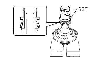
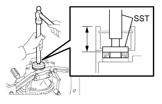
Using SST and a torque wrench, measure the total preload.
- SST
- 09326-20011
Total Preload (at Starting) Item Preload New bearing (without SST) 0.48 to 0.70 N*m (5 to 7 kgf*cm, 5 to 6 in.*lbf) + Driven pinion preload New bearing (with SST) 0.35 to 0.50 N*m (4 to 5 kgf*cm, 4 to 4.4 in.*lbf) + Driven pinion preload Reused bearing (without SST) 0.35 to 0.53 N*m (4 to 5 kgf*cm, 4 to 4.6 in.*lbf) + Driven pinion preload Reused bearing (with SST) 0.25 to 0.38 N*m (3 to 3.8 kgf*cm, 3 to 3.3 in.*lbf) + Driven pinion preload Tech Tips
-
Use a torque wrench with a fulcrum length of 130 mm (5.12 in.).
-
Turn the driven pinion counterclockwise and clockwise several times.
If the preload is outside the specified range, replace the No. 2 transfer ring gear mounting case washer with one that is thicker or thinner as necessary and recheck.
Text in Illustration *1 No. 2 Transfer Ring Gear Mounting Case Washer Washer Thickness: mm (in.) Mark Thickness Mark Thickness G7 2.47 (0.0972) M7 3.47 (0.1366) G8 2.49 (0.0980) M8 3.49 (0.1374) G9 2.51 (0.0988) M9 3.51 (0.1382) H0 2.53 (0.0996) N0 3.53 (0.1390) H1 2.55 (0.1004) N1 3.55 (0.1398) H2 2.57 (0.1012) N2 3.57 (0.1406) H3 2.59 (0.1020) N3 3.59 (0.1413) H4 2.61 (0.1028) N4 3.61 (0.1421) H5 2.63 (0.1035) N5 3.63 (0.1429) H6 2.65 (0.1043) N6 3.65 (0.1437) H7 2.67 (0.1051) N7 3.67 (0.1445) H8 2.69 (0.1059) N8 3.69 (0.1453) H9 2.71 (0.1067) N9 3.71 (0.1461) J0 2.73 (0.1075) P0 3.73 (0.1469) J1 2.75 (0.1083) P1 3.75 (0.1476) J2 2.77 (0.1091) P2 3.77 (0.1484) J3 2.79 (0.1098) P3 3.79 (0.1492) J4 2.81 (0.1106) P4 3.81 (0.1500) J5 2.83 (0.1114) P5 3.83 (0.1508) J6 2.85 (0.1122) P6 3.85 (0.1516) J7 2.87 (0.1130) P7 3.87 (0.1524) J8 2.89 (0.1138) P8 3.89 (0.1531) J9 2.91 (0.1146) P9 3.91 (0.1539) K0 2.93 (0.1154) Q0 3.93 (0.1547) K1 2.95 (0.1161) Q1 3.95 (0.1555) K2 2.97 (0.1169) Q2 3.97 (0.1563) K3 2.99 (0.1177) Q3 3.99 (0.1571) K4 3.01 (0.1185) Q4 4.01 (0.1579) K5 3.03 (0.1193) Q5 4.03 (0.1587) K6 3.05 (0.1201) Q6 4.05 (0.1594) K7 3.07 (0.1209) Q7 4.07 (0.1602) K8 3.09 (0.1217) Q8 4.09 (0.1610) K9 3.11 (0.1224) Q9 4.11 (0.1618) L0 3.13 (0.1232) R0 4.13 (0.1626) L1 3.15 (0.1240) R1 4.15 (0.1634) L2 3.17 (0.1248) R2 4.17 (0.1642) L3 3.19 (0.1256) R3 4.19 (0.1650) L4 3.21 (0.1264) R4 4.21 (0.1657) L5 3.23 (0.1272) R5 4.23 (0.1665) L6 3.25 (0.1280) R6 4.25 (0.1673) L7 3.27 (0.1287) R7 4.27 (0.1681) L8 3.29 (0.1295) R8 4.29 (0.1689) L9 3.31 (0.1303) R9 4.31 (0.1697) M0 3.33 (0.1311) S0 4.33 (0.1705) M1 3.35 (0.1319) S1 4.35 (0.1713) M2 3.37 (0.1327) S2 4.37 (0.1720) M3 3.39 (0.1335) S3 4.39 (0.1728) M4 3.41 (0.1343) S4 4.41 (0.1736) M5 3.43 (0.1350) S5 4.43 (0.1744) M6 3.45 (0.1358) S6 4.45 (0.1752) -
Using a chisel and a hammer, stake the gear nut.
-
-
INSTALL TRANSFER CASE FRONT OIL SEAL (for RH Side)
-
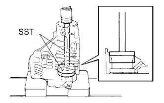
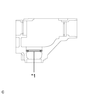
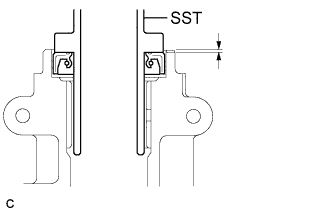
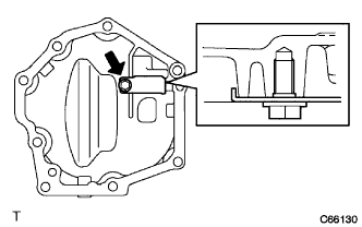
Using SST and a hammer, drive a new transfer case front oil seal (for RH side) into the transfer case until it reaches the position shown in the illustration.
- SST
- 09950-60010 ( 09951-00350, 09951-00580, 09952-06010 )
- 09950-70010 ( 09951-07150 )
Drive in depth 33.5 to 34.5 mm (1.319 to 1.358 in.) Note
Do not install the transfer case front oil seal (for RH side) at an angle.
-
Apply a small amount of MP grease to the lip of the transfer case front oil seal (for RH side).
-
-
INSTALL TRANSFER CASE FRONT OIL SEAL
-
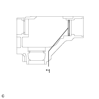
Using SST and a hammer, drive a new transfer case front oil seal into the transfer case until it reaches the position in the illustration.
- SST
- 09608-10010
- 09950-70010 ( 09951-07150 )
Drive in depth 9.5 to 10.5 mm (0.374 to 0.413 in.) -
Apply a small amount of MP grease to the lip of the transfer case front oil seal.
-
-
INSTALL TRANSFER CASE REAR OIL SEAL
-
Using SST and a hammer, drive a new transfer case rear oil seal into the transfer extension housing sub-assembly until it reaches the position shown in the illustration.
- SST
- 09325-20010
Drive in depth 1.1 to 1.9 mm (0.0433 to 0.0748 in.) -
Apply a small amount of MP grease to the lip of the transfer case rear oil seal.
-
-
INSTALL TRANSFER EXTENSION HOUSING DUST DEFLECTOR
-
Using SST and a press, press in a new transfer extension housing dust deflector until it contacts the installation surface as shown in the illustration.
- SST
- 09950-60020 ( 09951-00810 )
- 09950-70010 ( 09951-07150 )
-
-
INSTALL TRANSFER EXTENSION HOUSING SUB-ASSEMBLY
-
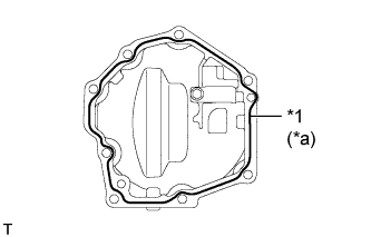
Text in Illustration *1 FIPG *a Seal Width 1.2 mm (0.0472 in.) Remove any FIPG material and be careful not to drop oil on the contact surfaces of the transfer extension housing sub-assembly and the transfer case.
-
Degrease the surfaces with a non-residue solvent.
-
Apply FIPG to the transfer extension housing sub-assembly.
FIPG Toyota Genuine Seal Packing 1281, Three Bond 1281 or equivalent -
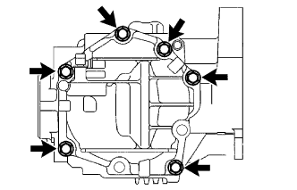
Install the transfer extension housing sub-assembly with the 4 bolts to the transfer case.
- Torque:
- 26 N*m { 260 kgf*cm, 19 ft.*lbf }
Note
Assemble the transfer extension housing sub-assembly within 10 minutes of FIPG application.
-
-
SEPARATE TRANSFER ASSEMBLY
-
Remove the transfer assembly from the overhaul attachment.
-
-
INSTALL TRANSFER CASE STRAIGHT PIN
-
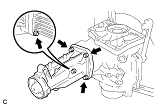
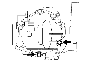
Using a plastic hammer, drive the 4 transfer case straight pins into the transfer case positions shown in the illustration.
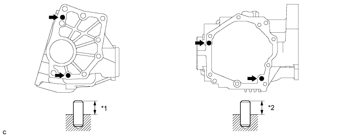
Text in Illustration *1 10.8 to 11.8 mm (0.425 to 0.465 in.) *2 5.7 to 6.7 mm (0.224 to 0.264 in.)
-
-
INSTALL TRANSFER DYNAMIC DAMPER
-
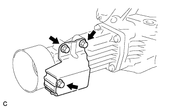
Install the transfer dynamic damper with the 3 bolts to the transfer extension housing sub-assembly.
- Torque:
- 26 N*m { 260 kgf*cm, 19 ft.*lbf }
-
-
INSTALL TRANSFER CASE BREATHER PLUG
-
Using SST and a hammer, tap in a new transfer case breather plug.
- SST
- 09820-00031
-
-
INSTALL BREATHER OIL DEFLECTOR
-
Install the breather oil deflector with the bolt.
- Torque:
- 6.5 N*m { 66 kgf*cm, 58 in.*lbf }
-
-
INSTALL NO. 1 TRANSFER CASE COVER
-
Text in Illustration *1 FIPG *a Seal Width 1.2 mm (0.0472 in.) Remove any FIPG material and be careful not to drop oil on the contact surfaces of the No. 1 transfer case cover and the transfer case.
-
Degrease the surfaces with a non-residue solvent.
-
Apply FIPG to the No. 1 transfer case cover.
FIPG Toyota Genuine Seal Packing 1281, Three Bond 1281 or equivalent -
Install the No. 1 transfer case cover with the 6 bolts.
- Torque:
- 20 N*m { 200 kgf*cm, 14 ft.*lbf }
Note
-
Wait for at least 1 hour after installing the No. 1 transfer case cover before adding transfer oil.
-
Assemble the No. 1 transfer case cover within 10 minutes of FIPG application.
-
Install the No. 1 transfer case cover with 2 new bolts.
- Torque:
- 20 N*m { 200 kgf*cm, 14 ft.*lbf }
-
-
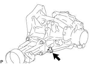
INSTALL TRANSFER DRAIN PLUG
-
Install a new gasket to the transfer drain plug.
-
Install the transfer drain plug to the transfer assembly.
- Torque:
- 49 N*m { 500 kgf*cm, 36 ft.*lbf }
-
-
INSTALL NO. 1 TRANSFER CASE PLUG
-
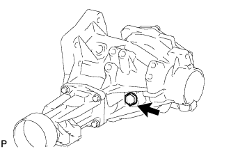
Install a new gasket to the No. 1 transfer case plug.
-
Install the No. 1 transfer case plug to the transfer assembly.
- Torque:
- 49 N*m { 500 kgf*cm, 36 ft.*lbf }
-
-
INSTALL NO. 2 TRANSFER CASE PLUG
-
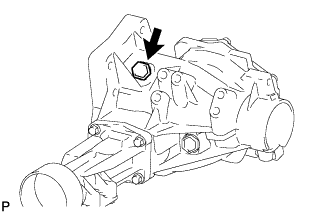
Install a new gasket to the No. 2 transfer case plug.
-
Install the No. 2 transfer case plug to the transfer assembly.
- Torque:
- 49 N*m { 500 kgf*cm, 36 ft.*lbf }
-
-
INSTALL TRANSFER AND TRANSAXLE SETTING STUD BOLT
-
Install 4 new transfer and transaxle setting stud bolts to the transfer case positions shown in the illustration.
- Torque:
- 30 N*m { 306 kgf*cm, 22 ft.*lbf }
Tech Tips
Install the shorter end of the transfer and transaxle setting stud bolts to the transfer assembly.
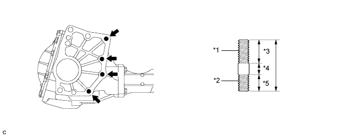
Text in Illustration *1 Transaxle Side *2 Transfer Side *3 30 mm (1.1811 in.) *4 12 mm (0.4724 in.) *5 22 mm (0.8661 in.) - -
-