TRANSFER ASSEMBLY DISASSEMBLY

-
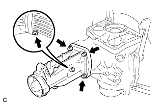
REMOVE TRANSFER AND TRANSAXLE SETTING STUD BOLT
-
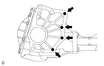
Remove the 4 transfer and transaxle setting stud bolts.
-
-
REMOVE NO. 2 TRANSFER CASE PLUG
-
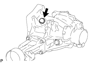
Remove the No. 2 transfer case plug.
-
Remove the gasket from the No. 2 transfer case plug.
-
-
REMOVE NO. 1 TRANSFER CASE PLUG
-
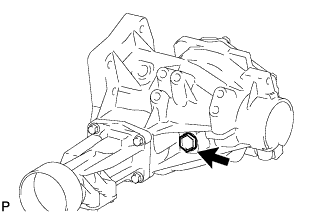
Remove the No. 1 transfer case plug.
-
Remove the gasket from the No. 1 transfer case plug.
-
-
REMOVE TRANSFER DRAIN PLUG
-
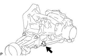
Remove the transfer drain plug.
-
Remove the gasket from the transfer drain plug.
-
-
REMOVE TRANSFER CASE BREATHER PLUG
-
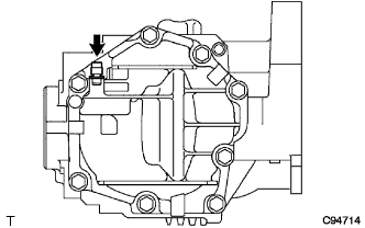
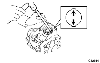
Using a screwdriver, remove the transfer case breather plug.
-
-
REMOVE NO. 1 TRANSFER CASE COVER
-
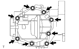
Remove the 8 bolts.
-
Using a brass bar and a hammer, remove the No. 1 transfer case cover from the transfer case.
Note
Place the brass bar on the rib protruding from the No. 1 transfer case cover.
-
-
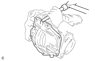
REMOVE BREATHER OIL DEFLECTOR
-
Remove the bolt and breather oil deflector.
-
-
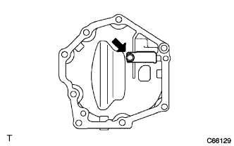
REMOVE TRANSFER DYNAMIC DAMPER
-
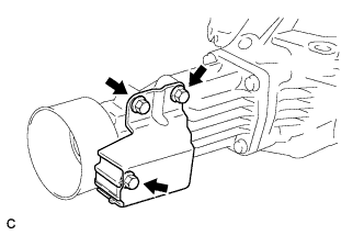
Remove the 3 bolts and transfer dynamic damper from the transfer extension housing sub-assembly.
-
-
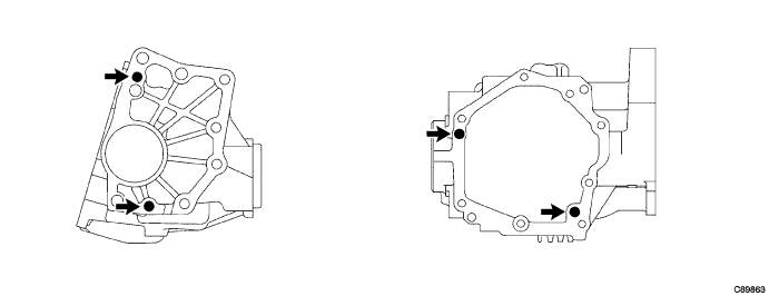
REMOVE TRANSFER CASE STRAIGHT PIN
-
Remove the 4 transfer case straight pins from the transfer case.
-
-
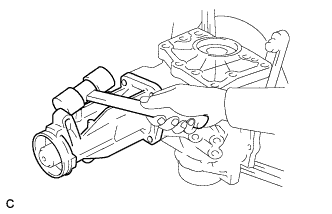
SECURE TRANSFER ASSEMBLY
-
Attach the transfer assembly to an overhaul attachment.
-
-
REMOVE TRANSFER EXTENSION HOUSING DUST DEFLECTOR
-
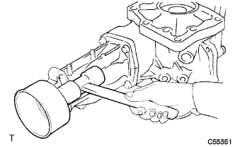
Using a plastic hammer, remove the transfer extension housing dust deflector from the transfer extension housing sub-assembly.
-
-
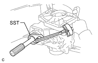
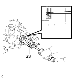
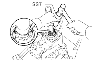
REMOVE TRANSFER CASE REAR OIL SEAL
-
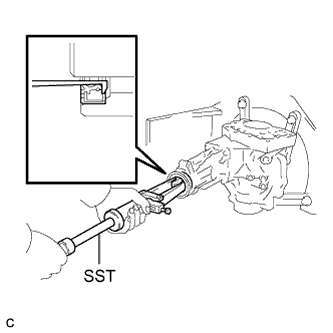
Using SST, remove the transfer case rear oil seal from the transfer extension housing sub-assembly.
- SST
- 09308-00010
Note
Be careful not to damage the transfer case rear oil seal contact surface or the inside surface of the transfer case rear oil seal.
-
-
REMOVE TRANSFER EXTENSION HOUSING SUB-ASSEMBLY
-
Remove the 4 bolts.
-
Using a plastic hammer, remove the transfer extension housing sub-assembly from the transfer case.
-
-
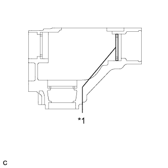
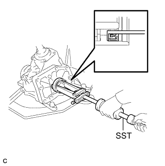
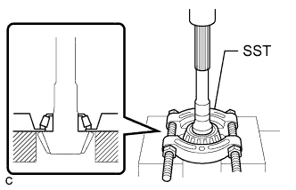
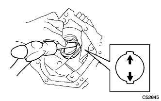
INSPECT PRELOAD
-
Text in Illustration *1 No. 2 Transfer Ring Gear Mounting Case Washer Using SST and a torque wrench, measure the preload of the backlash between the driven pinion and ring gear.
- SST
- 09326-20011
Preload (at Starting) Item Preload without SST 0.56 to 0.94 N*m (6 to 9 kgf*cm, 5 to 8 in.*lbf) with SST 0.40 to 0.67 N*m (4 to 6 kgf*cm, 4 to 5 in.*lbf) Tech Tips
-
Use a torque wrench with a fulcrum length of 130 mm (5.12 in.).
-
Turn the driven pinion counterclockwise and clockwise several times.
-
If the preload is too high, replace the transfer pinion bearing spacer with a new one.
-
If the preload is too low, tighten the gear nut further by turning it 5 to 10 degrees at a time, and then measure the preload again. Repeat this operation until the specified preload is obtained.
-
If the preload remains too low even after the gear nut has been tightened to a level in excess of the specified torque, loosen the gear nut and check its threads and those of the driven pinion for damage.
-
If there is no damage, replace the transfer pinion bearing spacer with a new one. Apply hypoid gear oil to the threads and repeat the steps above.
-
Write down the preload for use as a reference during the total preload measurement.
-
Using SST and a torque wrench, measure the total preload.
- SST
- 09326-20011
Preload (at Starting) Item Preload without SST 0.35 to 0.53 N*m (4 to 5 kgf*cm, 3 to 4 in.*lbf) + driven pinion preload with SST 0.25 to 0.38 N*m (3 to 4 kgf*cm, 3 to 3.3 in.*lbf) + driven pinion preload Tech Tips
-
Use a torque wrench with a fulcrum length of 130 mm (5.12 in.).
-
Turn the driven pinion counterclockwise and clockwise several times.
If the preload is outside the specified range, replace the No. 2 transfer ring gear mounting case washer with one that is thicker or thinner as necessary and recheck.
Washer Thickness: mm (in.) Mark Thickness Mark Thickness G7 2.47 (0.0972) M7 3.47 (0.1366) G8 2.49 (0.0980) M8 3.49 (0.1374) G9 2.51 (0.0988) M9 3.51 (0.1382) H0 2.53 (0.0996) N0 3.53 (0.1390) H1 2.55 (0.1004) N1 3.55 (0.1398) H2 2.57 (0.1012) N2 3.57 (0.1406) H3 2.59 (0.1020) N3 3.59 (0.1413) H4 2.61 (0.1028) N4 3.61 (0.1421) H5 2.63 (0.1035) N5 3.63 (0.1429) H6 2.65 (0.1043) N6 3.65 (0.1437) H7 2.67 (0.1051) N7 3.67 (0.1445) H8 2.69 (0.1059) N8 3.69 (0.1453) H9 2.71 (0.1067) N9 3.71 (0.1461) J0 2.73 (0.1075) P0 3.73 (0.1469) J1 2.75 (0.1083) P1 3.75 (0.1476) J2 2.77 (0.1091) P2 3.77 (0.1484) J3 2.79 (0.1098) P3 3.79 (0.1492) J4 2.81 (0.1106) P4 3.81 (0.1500) J5 2.83 (0.1114) P5 3.83 (0.1508) J6 2.85 (0.1122) P6 3.85 (0.1516) J7 2.87 (0.1130) P7 3.87 (0.1524) J8 2.89 (0.1138) P8 3.89 (0.1531) J9 2.91 (0.1146) P9 3.91 (0.1539) K0 2.93 (0.1154) Q0 3.93 (0.1547) K1 2.95 (0.1161) Q1 3.95 (0.1555) K2 2.97 (0.1169) Q2 3.97 (0.1563) K3 2.99 (0.1177) Q3 3.99 (0.1571) K4 3.01 (0.1185) Q4 4.01 (0.1579) K5 3.03 (0.1193) Q5 4.03 (0.1587) K6 3.05 (0.1201) Q6 4.05 (0.1594) K7 3.07 (0.1209) Q7 4.07 (0.1602) K8 3.09 (0.1217) Q8 4.09 (0.1610) K9 3.11 (0.1224) Q9 4.11 (0.1618) L0 3.13 (0.1232) R0 4.13 (0.1626) L1 3.15 (0.1240) R1 4.15 (0.1634) L2 3.17 (0.1248) R2 4.17 (0.1642) L3 3.19 (0.1256) R3 4.19 (0.1650) L4 3.21 (0.1264) R4 4.21 (0.1657) L5 3.23 (0.1272) R5 4.23 (0.1665) L6 3.25 (0.1280) R6 4.25 (0.1673) L7 3.27 (0.1287) R7 4.27 (0.1681) L8 3.29 (0.1295) R8 4.29 (0.1689) L9 3.31 (0.1303) R9 4.31 (0.1697) M0 3.33 (0.1311) S0 4.33 (0.1705) M1 3.35 (0.1319) S1 4.35 (0.1713) M2 3.37 (0.1327) S2 4.37 (0.1720) M3 3.39 (0.1335) S3 4.39 (0.1728) M4 3.41 (0.1343) S4 4.41 (0.1736) M5 3.43 (0.1350) S5 4.43 (0.1744) M6 3.45 (0.1358) S6 4.45 (0.1752)
-
-
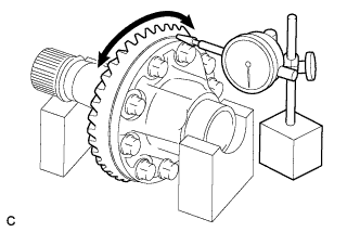
INSPECT RING GEAR BACKLASH
-
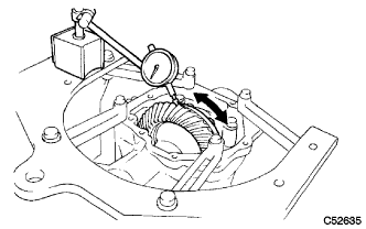
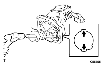
Using a dial indicator, check the backlash of the ring gear.
Backlash 0.14 to 0.25 mm (0.00551 to 0.00984 in.) If the backlash is not within the specification, adjust the side bearing preload or repair as necessary.
Note
Check at least 3 positions on the circumference of the ring gear.
-
-
INSPECT TOOTH CONTACT BETWEEN RING GEAR AND DRIVE PINION
-
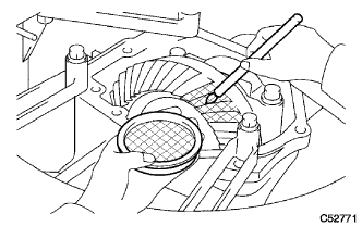
Coat 3 or 4 teeth at 4 different positions on the ring gear with Prussian blue.
-
Turn the driven pinion to rotate the ring gear 10 times or more clockwise and 10 times or more counterclockwise.
-
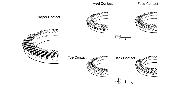
Rotate the ring gear to inspect the tooth pattern.
-
If the tooth contact pattern is not correct, select a new transfer output shaft washer that is thicker or thinner as necessary and recheck.
-
-
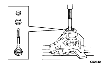
REMOVE TRANSFER CASE FRONT OIL SEAL
-
Using SST, remove the transfer case front oil seal from the transfer case.
- SST
- 09308-00010
Note
Do not damage the transfer case front oil seal contact surface on the transfer case.
-
-
REMOVE TRANSFER CASE FRONT OIL SEAL (for RH Side)
-
Using SST, remove the transfer case front oil seal (for RH side) from the transfer case.
- SST
- 09308-00010
Note
Do not damage the transfer case front oil seal (for RH side) contact surface on the transfer case.
-
-
REMOVE BEARING CAP
-
Remove the 2 bolts and bearing cap.
-
-
REMOVE NO. 1 TRANSFER OUTPUT SHAFT SPACER
-
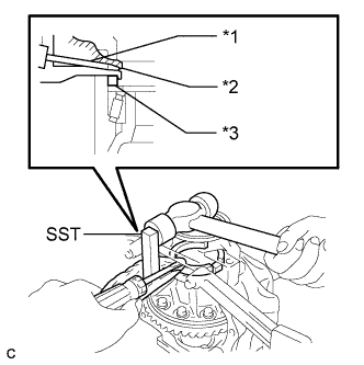
Text in Illustration *1 Screwdriver *2 Piece of Cloth *3 No. 1 Transfer Output Shaft Spacer Using SST, a screwdriver and a hammer, remove the No. 1 transfer output shaft spacer.
- SST
- 09504-22011
Note
Do not damage the transfer case.
-
-
REMOVE NO. 2 TRANSFER RING GEAR MOUNTING CASE WASHER
-
REMOVE TRANSFER RING GEAR MOUNTING CASE
-
Remove the transfer ring gear mounting case from the transfer case.
-
-
REMOVE DRIVEN PINION
-
Using SST and a hammer, unstake the gear nut.
- SST
- 09930-00010
Tech Tips
-
Use SST with the flat side facing outward.
-
Do not machine the tip of SST with a grinder, etc.
-
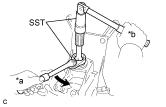
Text in Illustration *a Turn *b Hold Using SST, remove the gear nut.
- SST
- 09326-20011
- 09556-16030
-
Using a press, press out the driven pinion, transfer driven pinion rear bearing (inner race) and transfer pinion bearing spacer.
Note
-
Place a piece of cloth under the transfer case to prevent the driven pinion from dropping out of the transfer driven pinion rear bearing (inner race).
-
Use wooden blocks or similar objects under the transfer case to keep it level.
-
-
-
REMOVE TRANSFER DRIVEN PINION FRONT BEARING
-
Using SST and a press, press out the front transfer driven pinion bearing (inner race).
- SST
- 09950-00020
-
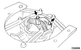
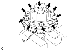
Using a brass bar and a hammer, tap the 2 positions shown in the illustration on the driven pinion front bearing (outer race) to remove it from the transfer case.
-
-
REMOVE TRANSFER OUTPUT SHAFT WASHER
-
REMOVE RING GEAR MOUNTING CASE BEARING
-
Remove the ring gear mounting case bearing (outer race) from the transfer ring gear mounting case.
-
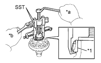
Text in Illustration *1 Ring Gear Mounting Case Bearing (Inner Race) *a Turn *b Hold Using SST, remove the ring gear mounting case bearing (inner race) from the transfer ring gear mounting case.
- SST
- 09950-40011 ( 09951-04010, 09952-04010, 09953-04020, 09954-04010, 09955-04061, 09957-04010, 09958-04011 )
- 09950-60010 ( 09951-00440 )
Note
Use SST (09953-04020) after applying grease to its threads and tip.
-
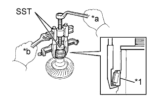
Text in Illustration *1 Ring Gear Mounting Case Bearing (Inner Race) *a Turn *b Hold Using SST, remove the ring gear mounting case bearing (inner race) from the transfer ring gear mounting case.
- SST
- 09950-40011 ( 09951-04010, 09952-04010, 09953-04020, 09954-04010, 09955-04061, 09957-04010, 09958-04011 )
- 09950-60010 ( 09951-00400 )
Note
Use SST (09953-04020) after applying grease to its threads and tip.
-
Using a brass bar and a hammer, tap the 2 positions shown in the illustration on the ring gear mounting case bearing (outer race) to remove it from the transfer case.
-
Remove the ring gear mounting case plate washer.
-
-
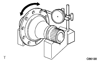
INSPECT RUNOUT OF RING GEAR
-
Place the transfer ring gear mounting case on the V-blocks.
-
Using a dial indicator, check the runout of the ring gear.
Maximum runout 0.06 mm (0.00236 in.) Tech Tips
If the runout is more than maximum, replace the ring gear with a new one.
-
-
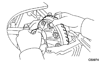
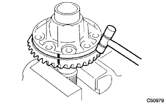
REMOVE RING GEAR
-
Text in Illustration *a Matchmark Put matchmarks on the transfer ring gear mounting case and ring gear.
-
Remove the 10 bolts.
-
Using a plastic hammer, tap on the ring gear to separate it from the transfer ring gear mounting case.
Note
Do not damage the ring gear teeth.
-
-
INSPECT TRANSFER RING GEAR MOUNTING CASE
-
Place the transfer ring gear mounting case on the V-blocks.
-
Using a dial indicator, check the runout of the transfer ring gear mounting case.
Maximum runout 0.04 mm (0.00157 in.) Tech Tips
If the runout is more than maximum, replace the transfer ring gear mounting case with a new one.
-
-
REMOVE TRANSFER DRIVEN PINION REAR BEARING
-
Using a brass bar and a hammer, tap the 2 positions shown in the illustration on the transfer driven pinion rear bearing (outer race) to remove it from the transfer case.
-