FRONT AXLE HUB REMOVAL

Tech Tips
-
Use the same procedure for the RH side and LH side.
-
The procedure listed below is for the LH side.
-
REMOVE FRONT WHEEL
-
REMOVE FRONT AXLE SHAFT NUT
-
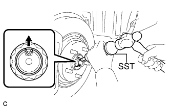
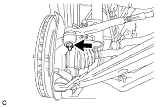
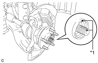
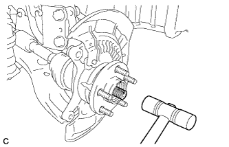
Using SST and a hammer, release the staked part of the front axle shaft nut.
- SST
- 09930-00010
Note
Loosen the staked part of the nut completely, otherwise the threads of the drive shaft may be damaged.
-
While applying the brakes, remove the front axle shaft nut.
-
-
SEPARATE FRONT SPEED SENSOR
-
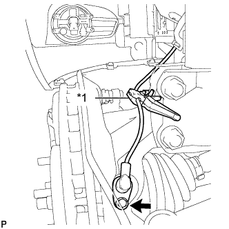
Text in Illustration *1 Resin Clamp Remove the bolt and resin clamp, and separate the front speed sensor.
Note
-
Prevent foreign matter from attaching to the front speed sensor tip.
-
Clean the speed sensor installation hole and the contact surfaces every time the front speed sensor is removed.
-
-
-
SEPARATE FRONT DISC BRAKE CALIPER ASSEMBLY
-
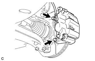
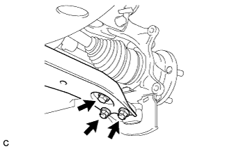
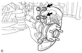
Remove the 2 bolts and separate the front disc brake caliper assembly.
Note
Use wire or an equivalent tool to keep the front disc brake caliper assembly from hanging down by the flexible hose.
-
-
REMOVE FRONT DISC
-
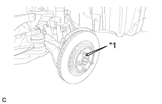
Text in Illustration *1 Matchmark Put matchmarks on the front disc and front axle hub.
Tech Tips
The above step is not necessary when the front disc will be replaced.
-
Remove the front disc.
-
-
SEPARATE TIE ROD ASSEMBLY
-
Remove the cotter pin and nut.
-
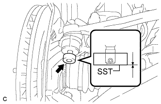
Install SST to the tie rod end.
- SST
- 09960-20010 ( 09961-02060 )
Note
Make sure that the upper ends of the tie rod end and SST are aligned.
-
Using SST, separate the tie rod end from the steering knuckle.
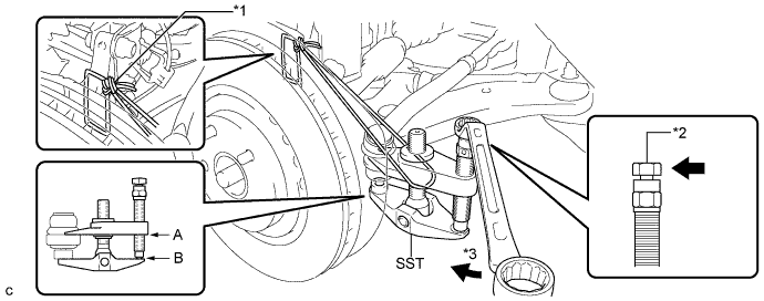
Text in Illustration *1 Tie the string without allowing for any slack. *2 Place the wrench here. *3 Turn - - - SST
- 09960-20010 ( 09961-02010 )
CAUTION:
Apply grease to the threads and end of the SST bolt.
Note
-
When securing SST to the steering knuckle, be sure to tighten the string of SST to prevent it from falling.
-
Install SST so that A and B are parallel.
-
Be sure to place a wrench on the part indicated in the illustration.
-
Do not damage the front disc brake dust cover.
-
Do not damage the ball joint dust cover.
-
Do not damage the steering knuckle.
-
-
SEPARATE FRONT LOWER SUSPENSION ARM
-
Remove the bolt and 2 nuts, and separate the front lower suspension arm from the front lower ball joint.
-
-
SEPARATE FRONT DRIVE SHAFT ASSEMBLY
-
Text in Illustration *1 Matchmark Put matchmarks on the front drive shaft assembly and front axle hub sub-assembly.
-
Using a plastic hammer, separate the front drive shaft assembly from the front axle assembly.
If it is difficult to separate, tap the end of the front drive shaft assembly using a brass bar and a hammer.
Note
Be careful not to damage the drive shaft boot and speed sensor rotor.
-
-
REMOVE FRONT AXLE ASSEMBLY
-
Remove the 2 bolts, 2 nuts and front axle assembly.
Note
-
When removing the nuts, keep the bolts from rotating.
-
Be careful not to damage the drive shaft boot and speed sensor rotor.
-
-
-
REMOVE FRONT NO. 1 WHEEL BEARING DUST DEFLECTOR
-
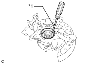
Text in Illustration *1 Vinyl Tape Using a screwdriver with its tip wrapped with vinyl tape, remove the front No. 1 wheel bearing dust deflector.
Note
Be careful not to damage the steering knuckle.
-
-
REMOVE FRONT AXLE HUB HOLE SNAP RING
-
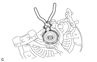
Using snap ring pliers, remove the front axle hub hole snap ring.
-
-
REMOVE FRONT AXLE HUB SUB-ASSEMBLY
-
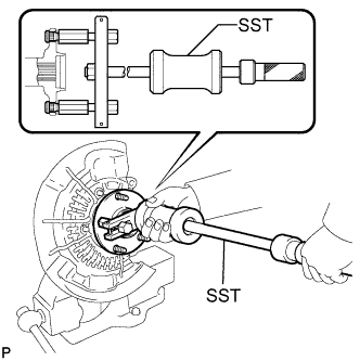
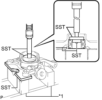
Hold the front axle assembly between aluminum plates in a vise.
Note
Do not overtighten the vise.
-
Using SST, remove the front axle hub sub-assembly.
- SST
- 09520-00031
-
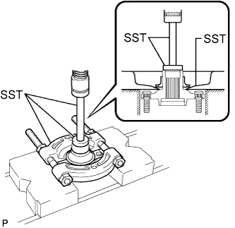
Using SST and a press, remove the bearing inner race (outside) from the front axle hub sub-assembly.
- SST
- 09555-55010
- 09950-60010 ( 09951-00430 )
- 09950-70010 ( 09951-07100 )
Note
Be careful not to drop the front axle hub sub-assembly.
-
-
REMOVE FRONT DISC BRAKE DUST COVER
-
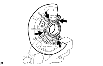
Remove the 4 bolts and front disc brake dust cover from the steering knuckle.
-
-
REMOVE FRONT AXLE HUB BEARING
-
Text in Illustration *1 V-block Place the bearing inner race (outside) on the front axle hub bearing.
-
Using SST, V-blocks and a press, remove the front axle hub bearing from the steering knuckle.
If the steering knuckle cannot be kept level using SST, stabilize the steering knuckle using a washer or an equivalent tool.
- SST
- 09527-21011
- 09950-60010 ( 09951-00440, 09952-06010 )
- 09950-60020 ( 09951-00750 )
- 09950-70010 ( 09951-07100 )
Note
Keep the steering knuckle level.
-