ACTIVE TORQUE CONTROL 4WD SYSTEM TC and CG Terminal Circuit
DESCRIPTION
Connecting terminals TC and CG of the DLC3 causes the AWD control ECU to display 2-digit DTCs by flashing the AWD warning light.
Tech Tips
When each warning light remains blinking, a short to ground in the wiring of terminal TC of the DLC3 or an internal short to ground in each ECU is suspected.
WIRING DIAGRAM
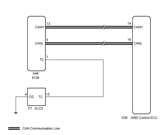
INSPECTION PROCEDURE
Tech Tips
Check the condition of each related circuit connector before troubleshooting Click here.
PROCEDURE
-
CHECK CAN COMMUNICATION SYSTEM
-
Check if the CAN communication DTC is output Click here.
Result Result Proceed to DTC is not output A DTC is output B
B 
REPAIR CAN COMMUNICATION SYSTEM Click here
A 
-
-
CHECK WIRE HARNESS (TC OF DLC3 - TC OF ECM AND BODY GROUND)
-
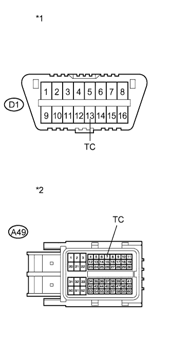
Text in Illustration *1 DLC3 *2 Front view of wire harness connector
(to ECM)
Turn the ignition switch off.
-
Disconnect the ECM connector.
-
Measure the resistance of the wire harness side connectors.
Standard Resistance Tester Connection
(DLC3 - ECM)
Condition Specified Condition D1-13 (TC) - A49-7 (TC) Always Below 1 Ω D1-13 (TC) - Body Ground Always 10 kΩ or higher
NG
REPAIR OR REPLACE HARNESS OR CONNECTOR
OK
-
-
CHECK WIRE HARNESS (CG OF DLC3 - BODY GROUND)
-
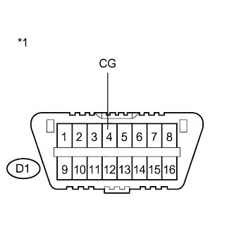
Text in Illustration *1 DLC3 Measure the resistance of the DLC3.
Standard Resistance Tester Connection Condition Specified Condition D1-4 (CG) - Body ground Always Below 1 Ω
NG
REPAIR OR REPLACE HARNESS OR CONNECTOR
OK
-
-
CHECK WIRE HARNESS (TC OF DLC3 - BODY GROUND)
-
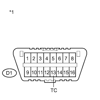
Text in Illustration *1 DLC3 Measure the resistance of the DLC3.
Standard Resistance Tester Connection Condition Specified Condition D1-13 (TC) - Body ground Always Below 1 Ω
NG
REPAIR OR REPLACE HARNESS OR CONNECTOR
OK 
REPLACE AWD CONTROL ECU Click here
-