ACTIVE TORQUE CONTROL 4WD SYSTEM, Diagnostic DTC:C1298/98

| DTC Code | DTC Name |
|---|---|
| C1298/98 | Linear Solenoid Circuit |
DESCRIPTION
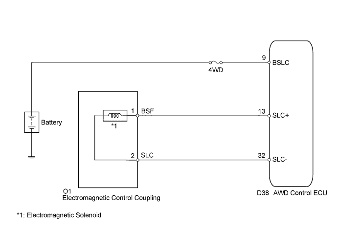
The AWD control ECU receives signals from each sensor to control clutch pressure to distribute torque according to the driving conditions.
| DTC No. | DTC Detection Condition | Trouble Area |
|---|---|---|
| C1298/98 | When the following continues for 1 second or more: - With the current of the 0.8 A or more, an open or short in the electromagnetic solenoid circuit occurs. |
|
WIRING DIAGRAM
INSPECTION PROCEDURE
Note
Inspect the fuses for circuits related to this system before performing the following inspection procedure.
Tech Tips
Check the condition of each related circuit connector before troubleshooting Click here.
PROCEDURE
-
CHECK WIRE HARNESS (AWD CONTROL ECU - BATTERY)
-
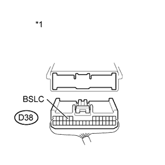
Text in Illustration *1 Rear view of wire harness connector
(to AWD Control ECU)
Disconnect the ECU connector.
-
Measure the voltage of the wire harness side connector.
Standard Voltage Tester Connection Condition Specified Condition D38-9 (BSLC) - Body Ground Always 11 to 14 V
NG 
REPAIR OR REPLACE HARNESS OR CONNECTOR
OK 
-
-
INSPECT ELECTRO MAGNETIC CONTROL COUPLING (ELECTROMAGNETIC SOLENOID)
-
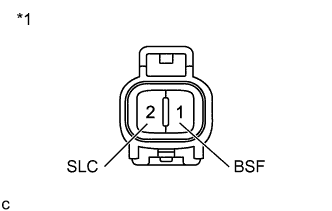
Text in Illustration *1 Electromagnetic Solenoid Remove the coupling connector.
-
Measure the resistance of the solenoid.
Standard Resistance Tester Connection Condition Specified Condition 1 (BSF) - 2 (SLC) Always 2.2 to 2.6 Ω 1 (BSF) - Body ground Always 10 kΩ or higher 2 (SLC) - Body ground Always 10 kΩ or higher
NG
REPLACE ELECTRO MAGNETIC CONTROL COUPLING Click here
OK
-
-
CHECK WIRE HARNESS (ELECTROMAGNETIC CONTROL COUPLING - AWD CONTROL ECU)
-
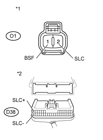
Text in Illustration *1 Front view of wire harness connector
(to Electromagnetic Solenoid)
*2 Rear view of wire harness connector
(to AWD Control ECU)
Disconnect the ECU connector.
-
Measure the resistance of the wire harness side connector.
Standard Resistance Tester Connection Condition Specified Condition D38-13 (SLC+) - O1-1 (BSF) Always Below 1 Ω D38-32 (SLC-) - O1-2 (SLC) Always Below 1 Ω D38-13 (SLC+) - Body ground Always 10 kΩ or higher D38-32 (SLC-) - Body ground Always 10 kΩ or higher
NG
REPAIR OR REPLACE HARNESS OR CONNECTOR
OK 
REPLACE AWD CONTROL ECU Click here
-