PROPELLER SHAFT ASSEMBLY INSTALLATION

-
TEMPORARILY TIGHTEN PROPELLER WITH CENTER BEARING SHAFT ASSEMBLY
-
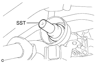
Remove SST from the transfer.
- SST
- 09325-20010
-
Install the propeller with center bearing shaft assembly.
Note
-
Be careful not to damage the oil seal.
-
Be careful not to damage the universal joint boot when installing the propeller shaft.
-
-
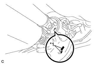
Text in Illustration *1 Matchmark Align the matchmarks on the rear propeller shaft and electromagnetic control coupling assembly and install the 4 nuts and 4 washers temporarily.
Note
Do not allow grease to adhere to be bolts or washers.
-
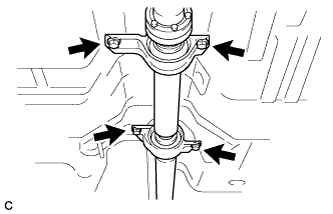
Temporarily install the propeller with center bearing shaft assembly with the 4 bolts, 2 No. 1 center support bearing washers and 2 No. 2 center support bearing washers.
Note
-
Reuse the washers.
-
Do not allow grease to adhere to be bolts or washers.
-
-
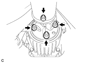
Fully tighten the 4 nuts.
- Torque:
- 37 N*m { 379 kgf*cm, 27 ft.*lbf }
-
-
FULLY TIGHTEN PROPELLER WITH CENTER BEARING SHAFT ASSEMBLY
- SST
- 09370-50010
-
Remove the piece of cloth or equivalent from the universal joint.
-
Depress the brake pedal and hold it.
-
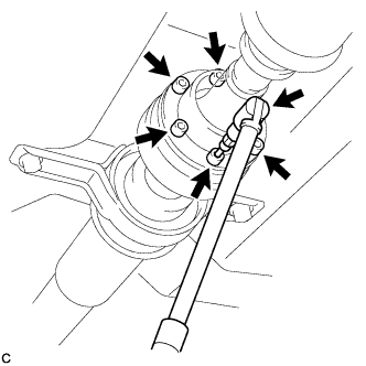
Using a hexagon wrench (6 mm), tighten the 6 bolts.
- Torque:
- 26 N*m { 265 kgf*cm, 19 ft.*lbf }
-
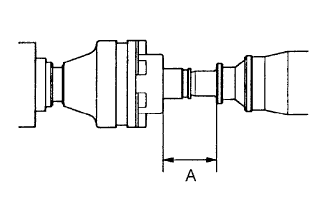
With the vehicle unloaded, adjust the dimension between the rear side of the cover and shaft as shown in the illustration.
Length A 65.5 to 70.5 mm (2.579 to 2.776 in.) -
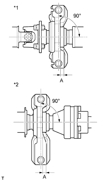
Text in Illustration *1 No. 1 Center Support Bearing Assembly *2 No. 2 Center Support Bearing Assembly With the vehicle unloaded, adjust the front and rear dimensions between the edge surface of the center support bearing and the edge surface of the cushion respectively as shown in the illustration, and then tighten the bolts.
Length A 11.5 to 13.5 mm (0.453 to 0.532 in.) -
Check that the center line of the bracket is at a right angle to the shaft axial direction.
-
Fully tighten the 4 bolts.
- Torque:
- 37 N*m { 375 kgf*cm, 27 ft.*lbf }
-
INSTALL CENTER EXHAUST PIPE ASSEMBLY
-
Install a new gasket to the center exhaust pipe assembly.
-
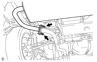
Connect the center exhaust pipe assembly to the 2 exhaust pipe supports.
-
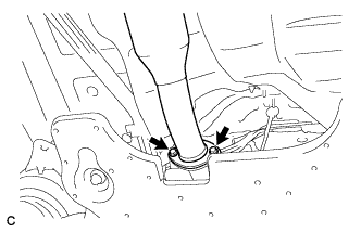
Install the center exhaust pipe assembly with the 2 bolts.
- Torque:
- 43 N*m { 438 kgf*cm, 32 ft.*lbf }
-
-
INSTALL TAIL EXHAUST PIPE ASSEMBLY
-
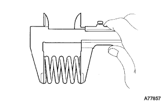
Using a vernier caliper, measure the free length of the compression springs.
Minimum length 38.5 mm (1.52 in.) If the free length is less than the minimum, replace the compression spring.
-
Fully insert a new gasket to the center exhaust pipe assembly.
-
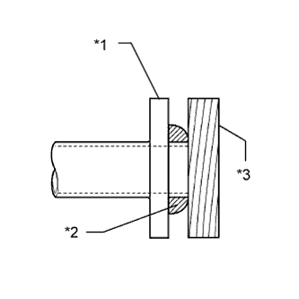
Text in Illustration *1 Center Exhaust Pipe Assembly *2 Gasket *3 Wooden Block Using a plastic hammer and wooden block, tap in the new gasket until its surface is flush with the center exhaust pipe assembly.
Note
-
Be sure to install the gasket in the correct direction.
-
Do not reuse the gasket.
-
Do not damage the gasket.
-
Do not push in the gasket by using the exhaust pipe when connecting it.
-
-
Connect the tail exhaust pipe assembly to the 4 exhaust pipe supports.
-
Install the tail exhaust pipe assembly with the 2 bolts and 2 compression springs.
- Torque:
- 43 N*m { 438 kgf*cm, 32 ft.*lbf }
-
-
INSPECT AND ADJUST TRANSFER OIL
-
INSPECT FOR EXHAUST GAS LEAK
-
INSPECT AND ADJUST JOINT ANGLE
-
If any vibration or noise occurs, perform joint angle check as follows and replace the No. 2 center support bearing washer with a proper one.
-
Turn the propeller shaft several times by hand to stabilize the center support bearings.
-
Using a jack, raise and lower the differential to stabilize the differential mounting cushion.
Note
Measure the joint angle while the vehicle is lifted using a 4 pillar lift or while working in a pit.
-
Remove the transfer dynamic damper.
-
Using SST, measure the propeller shaft installation angle (A) and intermediate shaft installation angle (B) as shown in the following illustration.
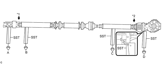
No. 1 joint angle (A) - (B) = -3.69° to -1.69° Text in Illustration *1 No. 1 joint angle *2 No. 4 joint angle -
Using SST, measure the rear propeller shaft installation angle (C) and rear differential installation angle (D) as shown in the preceding illustration.
No. 4 joint angle (C) - (D) = 1.63° to 3.63° -
If the calculated amount is not within the specification, adjust it with the No. 2 center support bearing washer.
Note
-
Make sure to use a washer of the same thickness on both right and left sides.
-
Do not use 2 or more washers on a bolt.
Washer Thickness Thickness mm (in.) 3.2 (0.126) 4.5 (0.177) 6.5 (0.256) 9.0 (0.354)
-
-
Install the transfer dynamic damper.
- Torque:
- 26 N*m { 265 kgf*cm, 19 ft.*lbf }
-
-