PARK / NEUTRAL POSITION SWITCH INSTALLATION

-
INSTALL PARK/NEUTRAL POSITION SWITCH ASSEMBLY
-
Move the shift lever to N.
-
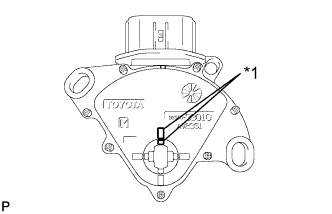
Text in Illustration *1 Protrusion Align the protrusions of the park/neutral position switch.
-
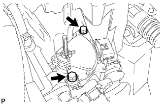
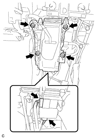
Install the park/neutral position switch to the control shaft with the 2 bolts.
- Torque:
- 5.4 N*m { 55 kgf*cm, 48 in.*lbf }
Note
-
Before installing the park/neutral position switch, remove any dirt or rust on the installation portion of the control shaft. Be sure to install the switch straight along the shaft while being careful not to deform the plate spring that supports the shaft. If the plate spring is deformed, the park/neutral position switch cannot be reinstalled correctly.
-
After installing the park/neutral position switch, confirm that the 2 protrusions on the switch are aligned.
-
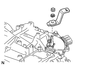
Install the control shaft lever to the control shaft with the nut and washer.
- Torque:
- 13 N*m { 130 kgf*cm, 9 ft.*lbf }
-
Connect the connector to the park/neutral position switch.
-
Connect the transmission control cable to the transmission control cable bracket with a new clip.
-
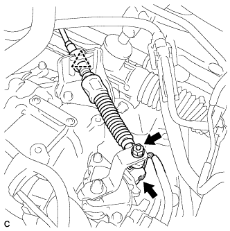
Connect the transmission control cable to the control shaft lever with the nut.
- Torque:
- 13 N*m { 130 kgf*cm, 9 ft.*lbf }
-
-
INSTALL AIR CLEANER BRACKET
-
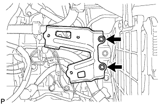
Install the air cleaner bracket with the 2 bolts.
- Torque:
- 7.8 N*m { 80 kgf*cm, 69 in.*lbf }
-
Install the wire harness clamp.
-
-
INSTALL AIR CLEANER CASE SUB-ASSEMBLY
-
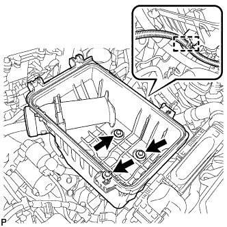
Install the air cleaner case sub-assembly with the 3 bolts.
- Torque:
- 5.0 N*m { 51 kgf*cm, 44 in.*lbf }
-
connect the wire harness clamp.
-
-
INSTALL AIR CLEANER FILTER ELEMENT SUB-ASSEMBLY
-
Install the air cleaner filter element sub-assembly.
-
-
INSTALL AIR CLEANER CAP SUB-ASSEMBLY
-
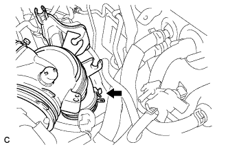
Connect the air-cleaner cap sub-assembly to the throttle body assembly and lock the hose band.
-
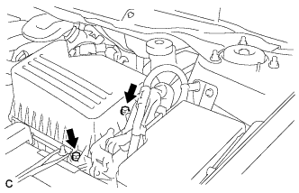
Install the air cleaner cap sub-assembly with the 2 bolts.
- Torque:
- 5.0 N*m { 51 kgf*cm, 44 in.*lbf }
-
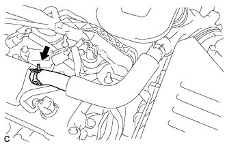
Connect the ventilation hose to the cylinder head cover.
-
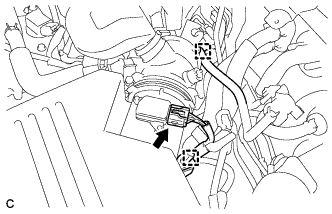
Connect the mass air flow meter connector and install the wire harness clamp to the air cleaner cap.
-
Install the hose to the hose clamp.
-
-
INSTALL INLET AIR CLEANER ASSEMBLY
-
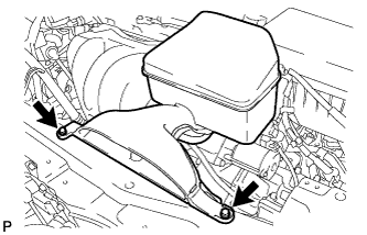
Install the inlet air cleaner assembly with the 2 bolts.
- Torque:
- 5.0 N*m { 51 kgf*cm, 44 in.*lbf }
-
-
INSTALL COOL AIR INTAKE DUCT SEAL
-
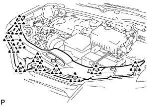
Install the cool air intake duct seal with the 12 clips.
-
-
INSPECT PARK/NEUTRAL POSITION SWITCH ASSEMBLY OPERATION
-
Apply the parking brake.
-
Turn the ignition switch to ON.
-
Depress the brake pedal and check that the engine starts when the shift lever is in N or P, but does not start in any other position.
-
Check that the back-up light comes on when the shift lever is moved to R, but the light does not operate in any other position. If the operation cannot be done as specified, check the park/neutral position switch for continuity.
-
-
INSPECT SHIFT LEVER POSITION
-
When moving the lever from P to R with the ignition switch ON and the brake pedal depressed, make sure that the shift lever moves smoothly and correctly into position.
-
Start the engine and make sure that the vehicle moves forward when moving the shift lever from N to D and moves rearward when moving the shift lever to R.
If the operation cannot be performed as specified, inspect the park/neutral position switch assembly and check the shift lever assembly installation condition.
-
-
ADJUST SHIFT LEVER POSITION
-
Apply the parking brake and move the shift lever to N.
-
Remove the console box sub-assembly Click here.
-
Disconnect the 2 connectors.
-
Remove the 4 nuts and shift lever assembly.
-
Disconnect the end of the transmission control cable assembly from the shift lever assembly.
-
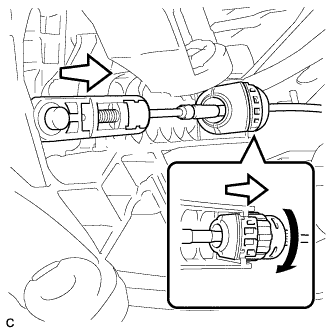
Turn the lock nut counterclockwise. While holding the lock nut, disconnect the transmission control cable from the shift lever retainer.
-
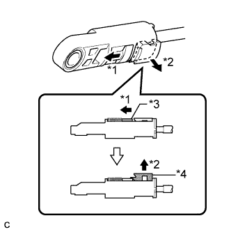
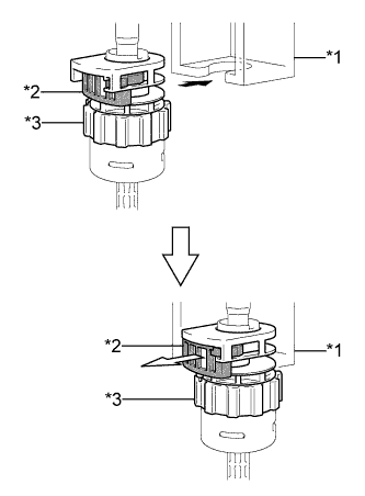
Text in Illustration *1 Slide *2 Pull *3 Slider *4 Lock Piece Slide the slider of the transmission control cable in the direction indicated by the arrow and pull the lock piece outward.
-
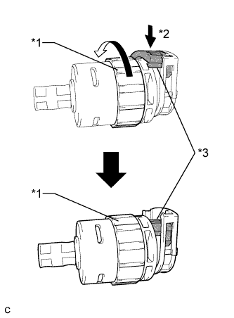
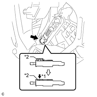
Text in Illustration *1 Lock Nut *2 Push in *3 Stopper Turn the lock nut of the transmission control cable counterclockwise. While holding the lock nut, push in the stopper.
-
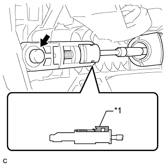
Text in Illustration *1 Shift Lever Retainer *2 Stopper *3 Lock Nut Connect the outer part of the transmission control cable to the shift lever retainer.
Note
The lock nut is fully seated against the shift lever retainer.
-
Text in Illustration *1 Lock Piece Install the transmission control cable end to the shift lever assembly.
Note
-
Check that the lock piece is pulled up.
-
Install the cable end all the way to the base of the pin.
-
-
Install the shift lever assembly with the 4 nuts.
- Torque:
- 12 N*m { 122 kgf*cm, 9 ft.*lbf }
-
Connect the 2 connectors.
-
Text in Illustration *1 Push *2 Lock Piece Push the lock piece into the adjuster case.
Note
Securely press in the lock piece until it locks.
-
After adjusting the shift lever position, check the operation and function of the shift lever. If there is a problem, adjust the position again.
-
Install the console box sub-assembly Click here.
-