DIFFERENTIAL CASE REASSEMBLY

-
INSTALL DIFFERENTIAL SIDE GEAR
-
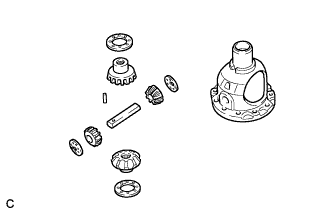
Coat the 2 front differential side gears, 2 No. 1 front differential side gear thrust washers, 2 front differential pinions and 2 front differential pinion thrust washers with ATF and install them to the differential case.
-
-
INSTALL FRONT NO. 1 DIFFERENTIAL PINION SHAFT
-
Coat the front No. 1 differential pinion shaft with ATF, and install it to the differential case.
-
-
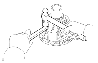
INSPECT DIFFERENTIAL SIDE GEAR BACKLASH
-
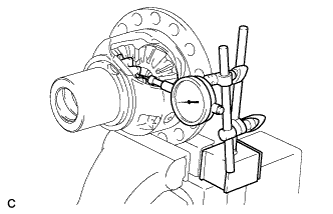
Hold the differential case in a vise between aluminum plates.
Note
Do not overtighten the vise.
-
Place a dial indicator on the tip of the differential side gear tooth at a right angle.
-
Hold the front differential pinion in the differential case and measure the backlash of the differential side gear.
Standard backlash 0 to 0.15 mm (0 to 0.00591 in.) Thrust Washer Thickness Thickness Thickness 1.50 mm (0.0591 in.) 1.75 mm (0.0689 in.) 1.55 mm (0.0610 in.) 1.80 mm (0.0709 in.) 1.60 mm (0.0630 in.) 1.85 mm (0.0728 in.) 1.65 mm (0.0650 in.) 1.90 mm (0.0748 in.) 1.70 mm (0.0669 in.) - If the backlash is greater than the standard range, select another No. 1 front differential side gear thrust washer.
-
-
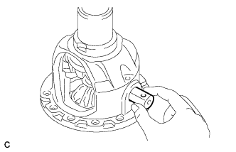
INSTALL FRONT DIFFERENTIAL PINION SHAFT STRAIGHT PIN
-
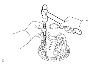
Using a 5 mm pin punch and hammer, install the front differential pinion shaft straight pin.
Note
Align the holes, and install the front differential pinion shaft straight pin.
-
Using a chisel and hammer, stake the differential case.
Note
Stake the differential case after adjusting the backlash.
-
-
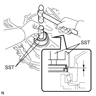
INSTALL FRONT DIFFERENTIAL CASE REAR TAPERED ROLLER BEARING
-
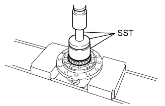
Using SST and a press, install a new front differential case rear tapered roller bearing to the differential case.
- SST
- 09710-30012 ( 09710-04081 )
- 09950-60010 ( 09951-00480 )
- 09950-70010 ( 09951-07100 )
Note
-
Do not damage the front differential case rear tapered roller bearing cage when installing front differential case rear tapered roller bearing.
-
Ensure that there is no clearance between the front differential case rear tapered roller bearing and differential case.
-
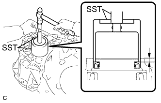
Using SST and a hammer, install a new front differential case rear tapered roller bearing outer race to the transaxle case.
- SST
- 09950-60020 ( 09951-00810 )
- 09950-70010 ( 09951-07150 )
Note
Ensure that there is no clearance between the front differential case rear tapered roller bearing outer race and transaxle case.
-
-
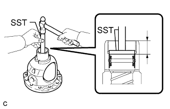
INSTALL FRONT DIFFERENTIAL CASE FRONT TAPERED ROLLER BEARING
-
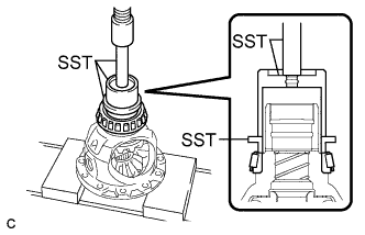
Using SST and a press, install a new front differential case front tapered roller bearing to the differential case.
- SST
- 09316-12010
- 09649-17010
- 09950-70010 ( 09951-07100 )
Note
-
Do not damage the front differential case front tapered roller bearing cage when installing front differential case front tapered roller bearing.
-
Ensure that there is no clearance between the front differential case front tapered roller bearing and differential case.
-
Install the shim to the transaxle housing.
-
Using SST and a hammer, install a new front differential case front tapered roller bearing outer race to the transaxle housing.
- SST
- 09950-60010 ( 09951-00910 )
- 09950-70010 ( 09951-07150 )
Note
Ensure that there is no clearance between the front differential case front tapered roller bearing outer race, shim and transaxle housing.
-
-
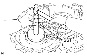
ADJUST DIFFERENTIAL SIDE BEARING PRELOAD
-
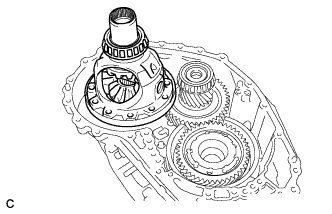
Install the differential assembly to the transaxle case.
-
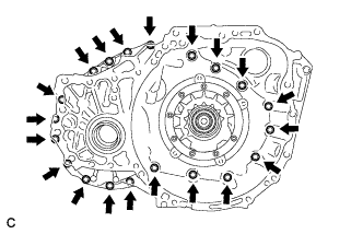
Clean the contact surfaces of the transaxle case and transaxle housing.
-
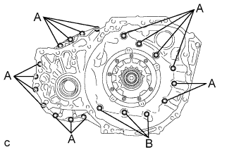
Install the transaxle housing to the transaxle case with the 20 bolts.
- Torque:
- Bolt A
- 31 N*m { 316 kgf*cm, 23 ft.*lbf }
- Bolt B
- 23 N*m { 234 kgf*cm, 17 ft.*lbf }
-
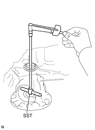
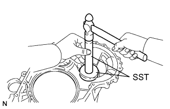
Using SST, turn the differential assembly right and left 2 or 3 times to settle the bearings.
- SST
- 09564-33010
-
Using SST and a torque wrench, measure the turning torque of the differential side bearings while rotating SST at 10 rpm.
- SST
- 09564-33010
Turning Torque 0.7 to 2.3 N*m (7 to 23 kgf*cm, 6 to 20 in.*lbf) If the turning torque is not within the specified range, refer to the table below to select a shim so that the turning torque is within the specified range.
Shim Thickness: mm (in.) Thickness Thickness Thickness Thickness 2.000 (0.0787) 2.225 (0.0876) 2.450 (0.0965) 2.675 (0.105) 2.025 (0.0797) 2.250 (0.0886) 2.475 (0.0974) 2.700 (0.106) 2.050 (0.0807) 2.275 (0.0896) 2.500 (0.0984) 2.725 (0.107) 2.075 (0.0817) 2.300 (0.0906) 2.525 (0.0994) 2.750 (0.108) 2.100 (0.0827) 2.325 (0.0915) 2.550 (0.100) 2.775 (0.109) 2.125 (0.0837) 2.350 (0.0925) 2.575 (0.101) 2.800 (0.110) 2.150 (0.0846) 2.375 (0.0935) 2.600 (0.102) 2.825 (0.111) 2.175 (0.0856) 2.400 (0.0945) 2.625 (0.103) 2.850 (0.112) 2.200 (0.0866) 2.425 (0.0955) 2.650 (0.104) 2.875 (0.113) -
Remove the 20 bolts and the transaxle housing from the transaxle case.
-
Remove the differential assembly from the transaxle case.
-
-
INSTALL FRONT DIFFERENTIAL RING GEAR
-
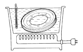
Using ATF and a heater, heat the front differential ring gear to 90 to 110°C (194 to 230°F).
Note
Do not heat the front differential ring gear to more than 110°C (230°F).
-
Clean the contact surface of the differential case.
-
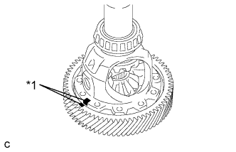
Text in Illustration *1 Matchmark Align the matchmarks, and install the front differential ring gear to differential case quickly.
Note
Do not install the bolts while the front differential ring gear is hot.
-
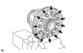
Install the 12 bolts.
- Torque:
- 120 N*m { 1223 kgf*cm, 88 ft.*lbf }
Note
Tighten the bolts incrementally in diagonal order.
-
-
INSTALL TRANSAXLE CASE OIL SEAL
-
Coat the lip of a new transaxle oil seal with MP grease.
-
Using SST and a hammer, install the transaxle oil seal to transaxle case.
- SST
- 09316-10010
- 09950-70010 ( 09951-07100 )
Standard Depth -0.5 to 0.5 mm (-0.0197 to 0.0197 in.)
-
-
INSTALL FRONT TRANSAXLE CASE OIL SEAL
-
Inside:
-
Coat the lip of a new front transaxle case oil seal with MP grease.
-
Using SST and a hammer, install the front transaxle case oil seal to differential case.
- SST
- 09950-60010 ( 09951-00410 )
- 09950-70010 ( 09951-07200 )
Standard Depth 21.5 to 22.5 mm (0.846 to 0.886 in.)
-
-
Outside:
-
Coat the lip of a new front transaxle case oil seal with MP grease.
-
Using SST and a hammer, install the front transaxle case oil seal to transaxle housing.
- SST
- 09649-17010
- 09950-70010 ( 09951-07200 )
Standard Depth 5.5 to 6.5 mm (0.217 to 0.256 in.) Note
Check that the front transaxle case oil seal is installed in the correct direction.
-
-