AUTOMATIC TRANSAXLE ASSEMBLY INSTALLATION

-
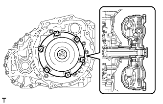
INSPECT TORQUE CONVERTER ASSEMBLY
-
Inspect the one-way clutch.
-
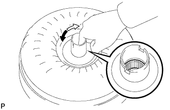
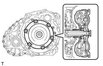
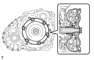
Press on the splines of the stator with a finger and rotate the spline. Check that the spline rotates smoothly when turned clockwise and rotates with difficulty when turned counterclockwise.
If necessary, clean the torque converter assembly and recheck the one-way clutch.
Replace the torque converter assembly if the one-way clutch still fails the inspection.
Text in Illustration 
Difficult 
Smooth
-
-
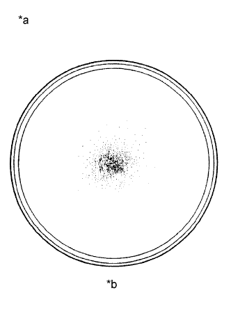
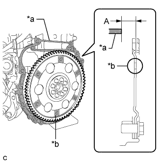
Text in Illustration *a Sample showing maximum allowable amount of powder in ATF *b Full Scale Inspect the torque converter assembly.
If any of the following problems are present, replace the torque converter assembly.
-
A metallic sound is emitted from the torque converter assembly during the stall test or when the shift lever is moved to N.
-
The one-way clutch turns smoothly or locks in both directions.
-
The amount of powder in the ATF is more than the sample shown in the illustration (refer to the sample).
Malfunction:
Tech Tips
The sample shows approximately 0.025 liters (0.026 US qts., 0.022 Imp. qts.) of ATF in Petri dish, which has been taken from the removed torque converter assembly.
-
-
Replace the ATF in the torque converter assembly.
Tech Tips
If the ATF is discolored or has a foul odor, stir the ATF in the torque converter assembly and drain it before replacing the ATF.
-
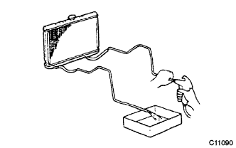
Clean and check the oil cooler and oil pipe line.
Tech Tips
-
If the torque converter assembly is inspected or the ATF is replaced, it is necessary to clean the oil cooler and oil pipe line.
-
Apply compressed air of 196 kPa (2.0 kgf/ cm2, 28 psi) into the inlet hose.
-
If a large amount of powder is found in the ATF, add new ATF using a bucket pump and clean the oil cooler and oil pipe line again.
-
If the ATF is cloudy, inspect the oil cooler.
-
-
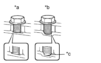
Text in Illustration *a Correct *b Incorrect *c Bottom is damaged Prevent deformation of the torque converter assembly and damage to the oil pump gear.
Note
Make sure that all of the bolts are the same length and that the specified bolts are used.
Tech Tips
If there is any damage to the tip of a bolt for the torque converter assembly or to the bottom of a bolt hole, replace the bolt and torque converter assembly.
-
-
INSTALL TORQUE CONVERTER ASSEMBLY
-
Engage the splines of the input shaft and turbine runner.
-
Engage the splines of the stator shaft and the stator while turning the torque converter assembly.
Tech Tips
If the stator shaft splines are difficult to engage with the stator splines, move the torque converter assembly back approximately 10 (0.394 in.) mm and engage the splines while rotating the torque converter assembly.
-
Turn the torque converter assembly to insert the key of the oil pump drive gear into the groove of the torque converter assembly.
-
Clean the torque converter assembly set bolt holes.
-
Text in Illustration *a Engine Surface *b Drive Plate Surface Using a vernier caliper and straightedge, measure dimension A between the transaxle contact surface of the engine and the torque converter assembly contact surface of the drive plate.
Note
Make sure to deduct the thickness of the straightedge.
-
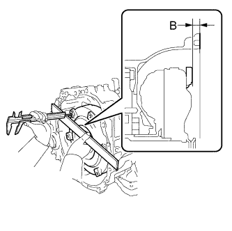
Using a vernier caliper and straightedge, measure dimension B shown in the illustration and check that dimension B is more than dimension A, which was measured in the previous step.
Standard A + 1 mm (0.0394 in.) or more Note
-
Make sure to deduct the thickness of the straightedge.
-
If the automatic transaxle assembly is installed to the engine with the torque converter assembly not sufficiently inserted, the torque converter assembly may be damaged.
-
-
-
INSTALL OUTLET NO. 1 OIL COOLER HOSE
-
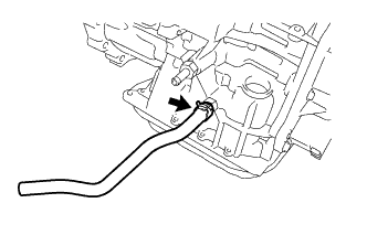
Install the outlet No. 1 oil cooler hose.
-
-
INSTALL INLET NO. 1 OIL COOLER HOSE
-
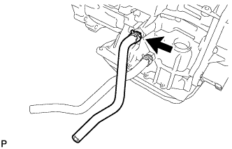
Install the inlet No. 1 oil cooler hose.
-
-
INSTALL TRANSMISSION CASE PLUG ASSEMBLY
-
Apply ATF to a new O-ring and install it to the transmission case plug assembly.
-
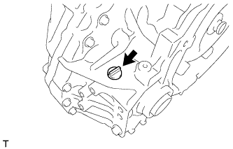
Install the transmission case plug assembly to the automatic transaxle assembly.
-
-
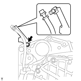
INSTALL NO. 1 TRANSMISSION CONTROL CABLE BRACKET
-
Install the No. 1 transmission control cable bracket to the automatic transaxle assembly with the 2 bolts.
- Torque:
- 12 N*m { 122 kgf*cm, 9 ft.*lbf }
-
-
INSTALL WIRE HARNESS CLAMP BRACKET
-
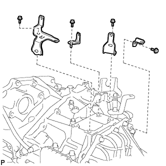
Install the 4 wire harness clamp brackets to the automatic transaxle assembly with the 4 bolts.
- Torque:
- 8.4 N*m { 86 kgf*cm, 74 in.*lbf }
-
-
INSTALL FRONT ENGINE MOUNTING BRACKET
-
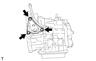
Install the front engine mounting bracket to the automatic transaxle assembly with the 3 bolts.
- Torque:
- 64 N*m { 653 kgf*cm, 47 ft.*lbf }
-
-
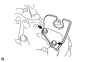
INSTALL FLEXIBLE HOSE BRACKET SUB-ASSEMBLY
-
Install the flexible hose bracket sub-assembly to the transaxle with the bolt.
- Torque:
- 20 N*m { 204 kgf*cm, 15 ft.*lbf }
-
Install the breather plug hose to the flexible hose bracket sub-assembly with the clip.
-
-
INSTALL AUTOMATIC TRANSAXLE ASSEMBLY
-
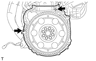
Confirm that the 2 knock pins are on the transaxle contact surface of the engine block before the transaxle installation.
-
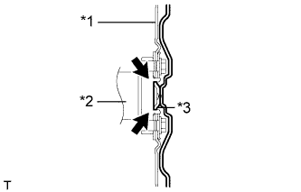
Text in Illustration *1 Drive Plate *2 Crankshaft *3 Torque Converter Assembly Centerpiece Apply clutch spline grease to the circumference of the crankshaft contact surface with the torque converter assembly centerpiece.
Clutch spline grease Toyota Genuine Clutch Splice Grease or equivalent Maximum spread About 1 g (0.0353 oz.) -
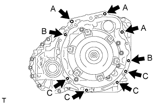
While keeping the engine and automatic transaxle assembly horizontal, align the knock pins with the holes in the automatic transaxle assembly and install the 9 bolts shown in the illustration.
- Torque:
- Bolt A
- 64 N*m { 653 kgf*cm, 47 ft.*lbf }
- Bolt B
- 46 N*m { 469 kgf*cm, 34 ft.*lbf }
- Bolt C
- 44 N*m { 449 kgf*cm, 32 ft.*lbf }
Note
-
Do not forcibly pry on the automatic transaxle assembly.
-
Check that the torque converter assembly rotates.
Tech Tips
Bolt length:
-
Bolt A: 55 mm (2.17 in.)
-
Bolt B: 50 mm (1.97 in.)
-
Bolt C: 32 or 33 mm (1.26 or 1.30 in.)
-
-
INSTALL WIRE HARNESS
-
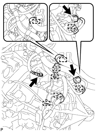
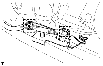
Connect the 6 wire harness clamps and park/neutral position switch connector.
-
Install the ground cable with the bolt.
- Torque:
- 12 N*m { 122 kgf*cm, 9 ft.*lbf }
-
-
INSTALL TCM
-
Install the TCM to the transaxle.
-
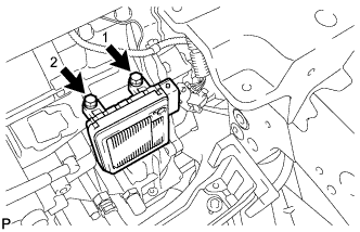
Install and tighten the 2 bolts in the order shown in the illustration.
- Torque:
- 11 N*m { 115 kgf*cm, 8 ft.*lbf }
-
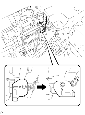
Connect the connector to the TCM.
-
Turn the lock lever and secure the connector with the lock lever.
-
-
INSTALL FRONT FRAME ASSEMBLY
-
Set the engine assembly with transaxle to the front frame assembly.
-
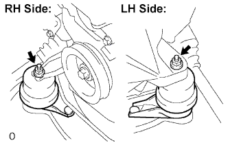
Install the engine mounting insulators RH and LH with the 2 nuts.
- Torque:
- 95 N*m { 968 kgf*cm, 70 ft.*lbf }
-
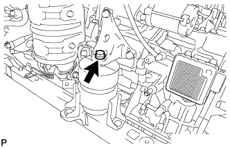
Install the front engine mounting insulator with the bolt.
- Torque:
- 87 N*m { 887 kgf*cm, 64 ft.*lbf }
-
Connect the 2 clamps with the engine wire.
-
-
INSTALL STARTER ASSEMBLY
-
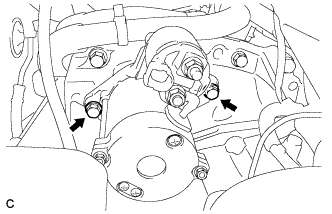
Install the starter with the 2 bolts.
- Torque:
- 37 N*m { 377 kgf*cm, 27 ft.*lbf }
-
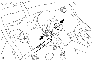
Connect the starter connector.
-
Install the terminal nut and cover the nut with the cap.
- Torque:
- 9.8 N*m { 100 kgf*cm, 87 in.*lbf }
-
-
INSTALL ENGINE ASSEMBLY WITH TRANSAXLE
Tech Tips
See the steps from "Install Engine Assembly with Transaxle" through "Inspect Speed Sensor Signal" Click here.
-
CHECK AUTOMATIC TRANSAXLE SYSTEM
Note
If automatic transmission parts have been replaced, refer to Parts Replacement Compensation Table to determine if any additional operations are necessary Click here.