SHIFT LEVER INSTALLATION

-
INSTALL SHIFT LEVER ASSEMBLY
Note
Check that the park/neutral position switch and the shift lever are in neutral.
-
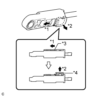
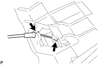
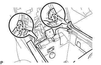
Text in Illustration *1 Slide *2 Pull *3 Slider *4 Lock Piece Slide the slider of the transmission control cable in the direction indicated by the arrow and pull the lock piece outward.
-
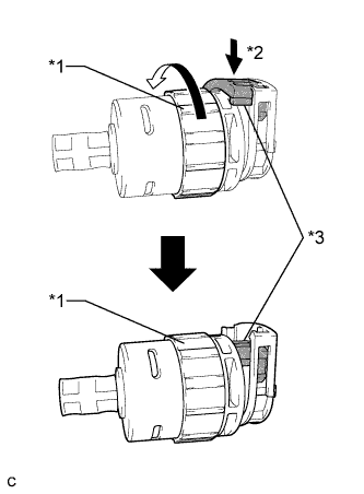
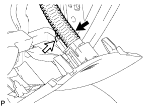
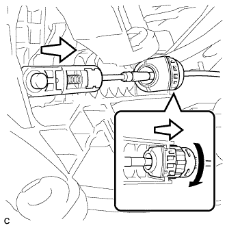
Text in Illustration *1 Lock Nut *2 Push in *3 Stopper Turn the lock nut of the transmission control cable counterclockwise. While holding the lock nut, push in the stopper.
-
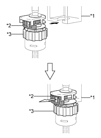
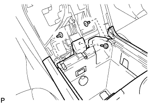
Text in Illustration *1 Shift Lever Retainer *2 Stopper *3 Lock Nut Connect the outer part of the transmission control cable to the shift lever retainer.
Note
The lock nut is fully seated against the shift lever retainer.
-
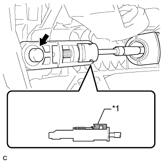
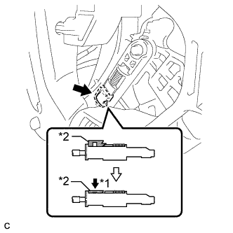
Text in Illustration *1 Lock Piece Install the transmission control cable end to the shift lever assembly.
Note
-
Check that the lock piece is pulled up.
-
Install the cable end all the way to the base of the pin.
-
-
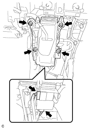
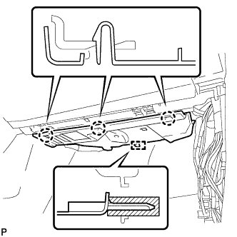
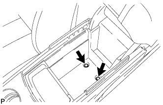
Install the shift lever assembly with the 4 nuts.
- Torque:
- 12 N*m { 122 kgf*cm, 9 ft.*lbf }
-
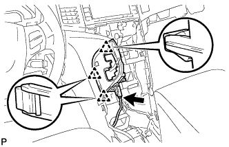
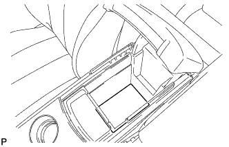
Connect the 2 connectors.
-
Text in Illustration *1 Push *2 Lock Piece Push the lock piece into the adjuster case.
Note
Securely push in the lock piece until the slider lock is engaged.
-
-
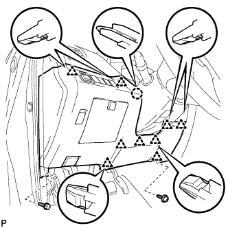
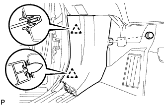
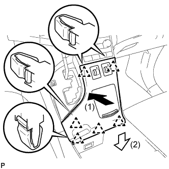
INSTALL CONSOLE BOX SUB-ASSEMBLY
-
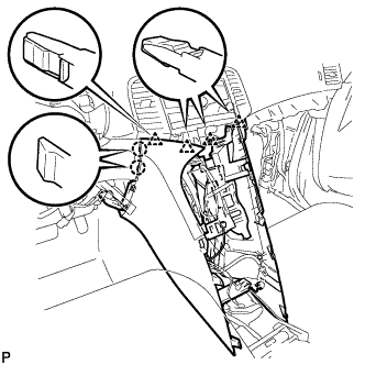
Engage the 2 claws and 4 clips.
-
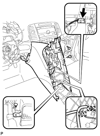
Engage the 2 clamps.
-
Connect the connector.
-
Install the clip.
-
Install the console box sub-assembly with the 2 screws <E> or <F>.
-
-
INSTALL POSITION INDICATOR HOUSING ASSEMBLY
-
Engage the 3 clips to position indicator housing assembly.
-
Connect the connector.
-
Move the shift lever to P.
-
-
INSTALL SHIFT LEVER KNOB SUB-ASSEMBLY
-
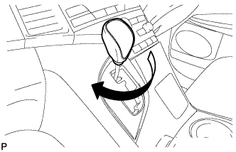
Turn the shift lever knob clockwise to install the shift lever knob sub-assembly.
-
-
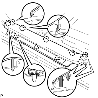
INSTALL LOWER INSTRUMENT PANEL SUB-ASSEMBLY
-
Connect the connectors.
-
Engage the 5 guides, 2 clips and claw.
-
Install the lower instrument panel sub-assembly with the bolt <C> and 4 screws <E> or <F>.
-
-
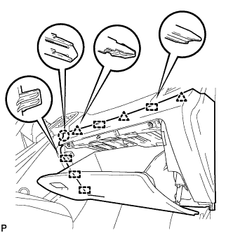
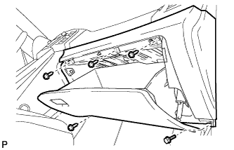
INSTALL NO. 2 INSTRUMENT PANEL UNDER COVER SUB-ASSEMBLY
-
Engage the guide and 3 claws to install the No. 2 instrument panel under cover sub-assembly.
-
-
INSTALL COWL SIDE TRIM SUB-ASSEMBLY RH
Tech Tips
Use the same procedure as for the LH side Click here.
-
INSTALL FRONT DOOR SCUFF PLATE RH
Tech Tips
Use the same procedure as for the LH side Click here.
-
INSTALL LOWER NO. 1 INSTRUMENT PANEL FINISH PANEL
-
Connect the hood lock control cable.
-
Connect the aspirator duct and connector.
-
Connect the connectors.
-
Engage the claw and 9 clips.
-
Install the lower No. 1 instrument panel finish panel with the bolt <C> and screw <E> or <F>.
-
-
INSTALL COWL SIDE TRIM SUB-ASSEMBLY LH
-
Engage the 2 clips to install the cowl side trim sub-assembly LH.
-
Install the clip.
-
-
INSTALL FRONT DOOR SCUFF PLATE LH
-
Engage the guide, 3 clips and the 7 claws to install the front door scuff plate LH.
-
-
INSTALL AIR CONDITIONING CONTROL ASSEMBLY
-
Connect the connector.
-
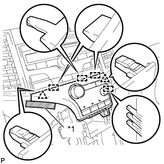
Engage the 2 clips and 4 guides.
-
Remove the protective tape.
Text in Illustration *1 Protective Tape -
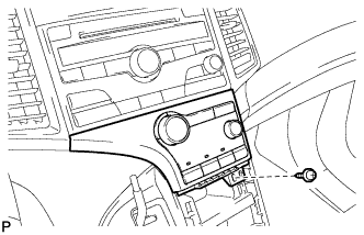
Install the air conditioning control assembly with the screw.
-
-
INSTALL CONSOLE BOX ASSEMBLY
-
Connect the connectors.
-
Engage the 2 claws.
-
Install the screw and 2 clips.
-
Install the console box assembly with the 2 bolts.
-
-
INSTALL NO. 2 CONSOLE BOX CARPET
-
Install the No. 2 console box carpet.
-
-
INSTALL UPPER CONSOLE PANEL SUB-ASSEMBLY
-
Connect the connectors.
-
Engage the 6 clips to install the upper console panel sub-assembly as shown in the illustration.
-
-
CONNECT CABLE TO NEGATIVE BATTERY TERMINAL
Note
When disconnecting the cable, some systems need to be initialized after the cable is reconnected Click here.
-
INSPECT SHIFT LEVER POSITION
-
When moving the lever from P to R with the ignition switch ON and the brake pedal depressed, make sure that the shift lever moves smoothly and correctly into position.
-
Start the engine and make sure that the vehicle moves forward when moving the shift lever from N to D and moves rearward when moving the shift lever to R.
If the operation cannot be performed as specified, inspect the park/neutral position switch assembly and check the shift lever assembly installation condition.
-
-
ADJUST SHIFT LEVER POSITION
-
Apply the parking brake and move the shift lever to N.
-
Remove the console box sub-assembly Click here.
-
Disconnect the 2 connectors.
-
Remove the 4 nuts and shift lever assembly.
-
Disconnect the end of the transmission control cable assembly from the shift lever assembly.
-
Turn the lock nut counterclockwise. While holding the lock nut, disconnect the transmission control cable from the shift lever retainer.
-
Text in Illustration *1 Slide *2 Pull *3 Slider *4 Lock Piece Slide the slider of the transmission control cable in the direction indicated by the arrow and pull the lock piece outward.
-
Text in Illustration *1 Lock Nut *2 Push in *3 Stopper Turn the lock nut of the transmission control cable counterclockwise. While holding the lock nut, push in the stopper.
-
Text in Illustration *1 Shift Lever Retainer *2 Stopper *3 Lock Nut Connect the outer part of the transmission control cable to the shift lever retainer.
Note
The lock nut is fully seated against the shift lever retainer.
-
Text in Illustration *1 Lock Piece Install the transmission control cable end to the shift lever assembly.
Note
-
Check that the lock piece is pulled up.
-
Install the cable end all the way to the base of the pin.
-
-
Install the shift lever assembly with the 4 nuts.
- Torque:
- 12 N*m { 122 kgf*cm, 9 ft.*lbf }
-
Connect the 2 connectors.
-
Text in Illustration *1 Push *2 Lock Piece Push the lock piece into the adjuster case.
Note
Securely press in the lock piece until it locks.
-
After adjusting the shift lever position, check the operation and function of the shift lever. If there is a problem, adjust the position again.
-
Install the console box sub-assembly Click here.
-