CRUISE CONTROL SYSTEM TC and CG Terminal Circuit
DESCRIPTION
Connecting terminals TC and CG of the DLC3 causes the system to enter self-diagnostic mode. If a malfunction is present, the MIL will blink.
Tech Tips
When a particular warning light remains blinking, a ground short in the wiring of terminal TC of the DLC3 or an internal ground short in the relevant ECU is suspected.
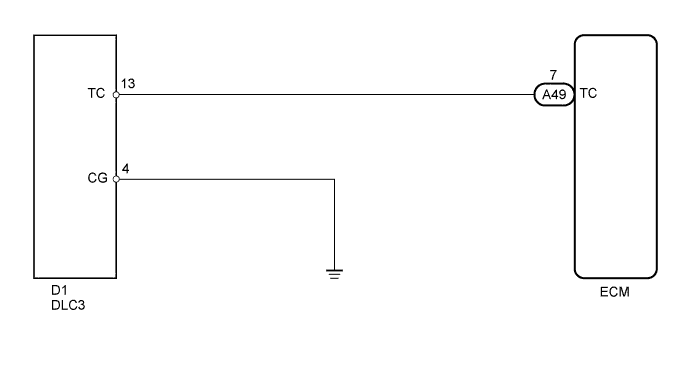
WIRING DIAGRAM
INSPECTION PROCEDURE
PROCEDURE
-
CHECK HARNESS AND CONNECTOR (DLC3 - ECM)
-
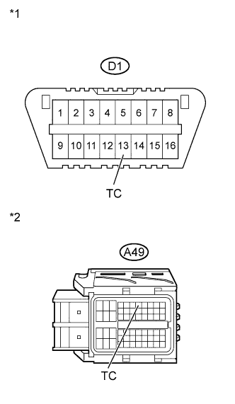
Text in Illustration *1 DLC3 *2 Front view of wire harness connector
(to ECM)
Disconnect the ECM connector.
-
Measure the resistance according to the value(s) in the table below.
Standard Resistance Tester Connection Condition Specified Condition D1-13 (TC) - A49-7 (TC) Always Below 1 Ω -
Reconnect the ECM connector.
NG 
REPAIR OR REPLACE HARNESS OR CONNECTOR (DLC3 - ECM)
OK 
-
-
CHECK HARNESS AND CONNECTOR (DLC3 - BODY GROUND)
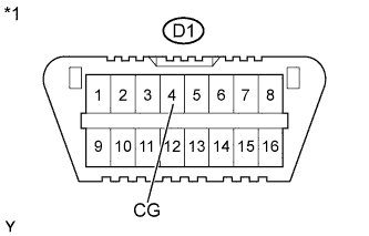
Text in Illustration *1 DLC3
-
Measure the resistance according to the value(s) in the table below.
Standard Resistance Tester Connection Condition Specified Condition D1-4 (CG) - Body ground Always Below 1 Ω
NG
REPAIR OR REPLACE HARNESS OR CONNECTOR (DLC3 - BODY GROUND)
OK
-
-
CHECK HARNESS AND CONNECTOR (DLC3 - BODY GROUND)
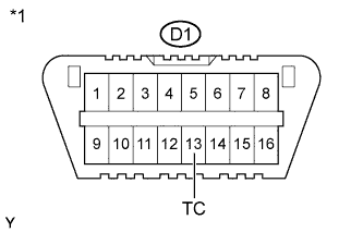
Text in Illustration *1 DLC3
-
Measure the resistance according to the value(s) in the table below.
Standard Resistance Tester Connection Condition Specified Condition D1-13 (TC) - Body ground Always 10 kΩ or higher
NG
REPAIR OR REPLACE HARNESS OR CONNECTOR OR EACH ECU
OK 
PROCEED TO NEXT SUSPECTED AREA SHOWN IN PROBLEM SYMPTOMS TABLE Click here
-