AUTOMATIC TRANSAXLE SYSTEM ECU Power Source Circuit
DESCRIPTION
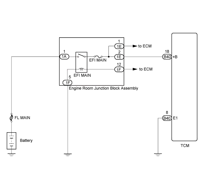
When the ignition switch is turned to ON, voltage from the ECM's MREL terminal is applied to the EFI MAIN relay. This causes the contacts of the EFI MAIN relay to close, which supplies power to terminal +B of the TCM.
WIRING DIAGRAM
INSPECTION PROCEDURE
PROCEDURE
-
CHECK HARNESS AND CONNECTOR (TCM - BODY GROUND)
-
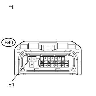
Text in Illustration *1 Front view of wire harness connector
(to TCM)
Turn the ignition switch off.
-
Disconnect the TCM connector.
-
Measure the resistance according to the value(s) in the table below.
Standard Resistance Tester Connection Condition Specified Condition B40-8 (E1) - Body ground Always Below 1 Ω
NG 
REPAIR OR REPLACE HARNESS OR CONNECTOR
OK 
-
-
INSPECT ECU TERMINAL VOLTAGE (+B TERMINAL)
-
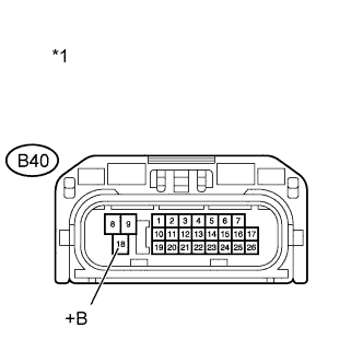
Text in Illustration *1 Front view of wire harness connector
(to TCM)
Disconnect the TCM connector.
-
Turn the ignition switch to ON.
-
Measure the voltage according to the value(s) in the table below.
Standard Voltage Tester Connection Switch Condition Specified Condition B40-18 (+B) - Body ground Ignition switch ON 11 to 14 V
NG 
CHECK HARNESS AND CONNECTOR (TCM - ENGINE ROOM JUNCTION BLOCK ASSEMBLY) Click here
OK 
PROCEED TO NEXT SUSPECTED AREA SHOWN IN PROBLEM SYMPTOMS TABLE Click here
-
-
CHECK HARNESS AND CONNECTOR (TCM - ENGINE ROOM JUNCTION BLOCK ASSEMBLY)
-
Turn the ignition switch off.
-
Disconnect the TCM connector.
-
Remove the engine room junction block assembly from the engine room relay block.
-
Measure the resistance according to the value(s) in the table below.
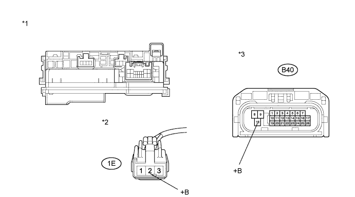
Standard Resistance (Check for Open) Tester Connection Condition Specified Condition B40-18 (+B) - 1E-2 (+B) Always Below 1 Ω Standard Resistance (Check for Short) Tester Connection Condition Specified Condition B40-18 (+B) or 1E-2 (+B) - Body ground Always 10 kΩ or higher Text in Illustration *1 Engine Room Junction Block Assembly *2 Front view of wire harness connector
(to Engine Room Junction Block Assembly)
*3 Front view of wire harness connector
(to TCM)
NG
REPAIR OR REPLACE HARNESS OR CONNECTOR
OK
-
-
INSPECT ENGINE ROOM JUNCTION BLOCK ASSEMBLY
-
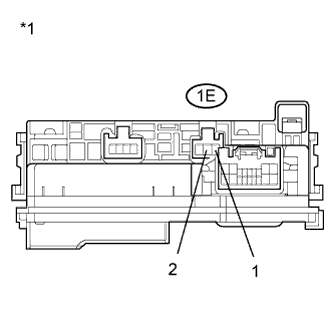
Text in Illustration *1 Component without harness connected
(Engine Room Junction Block Assembly)
Measure the resistance according to the value(s) in the table below.
Standard Resistance Tester Connection Condition Specified Condition 1E-1 - 1E-2 Always Below 1 Ω
NG
REPLACE ENGINE ROOM JUNCTION BLOCK ASSEMBLY
OK
GO TO ECM POWER SOURCE CIRCUIT (ENGINE CONTROL SYSTEM / SFI SYSTEM) Click here
-