ENGINE SWITCH REMOVAL

-
DISCONNECT CABLE FROM NEGATIVE BATTERY TERMINAL
Note
When disconnecting the cable, some systems need to be initialized after the cable is reconnected Click here.
-
REMOVE UPPER CONSOLE PANEL SUB-ASSEMBLY
-
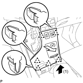
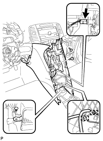
Pull the upper console panel sub-assembly in the direction indicated by the arrow to disengage the 6 clips.
-
Disconnect the connectors and remove the upper console panel sub-assembly.
-
-
REMOVE NO. 2 CONSOLE BOX CARPET
-
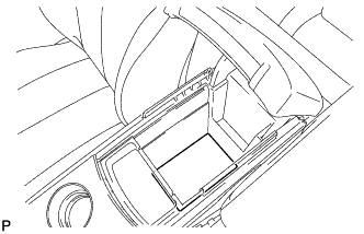
Remove the No. 2 console box carpet.
-
-
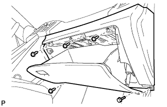
REMOVE CONSOLE BOX ASSEMBLY
-
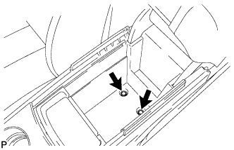
Remove the 2 bolts.
-
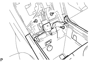
Remove the screw and 2 clips.
-
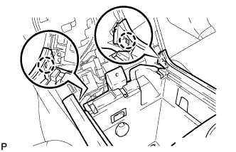
Disengage the 2 claws.
-
Disconnect the connectors and remove the console box assembly.
-
-
REMOVE AIR CONDITIONING CONTROL ASSEMBLY
-
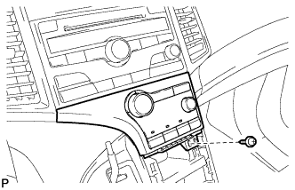
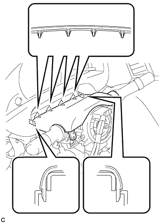
Remove the screw.
-
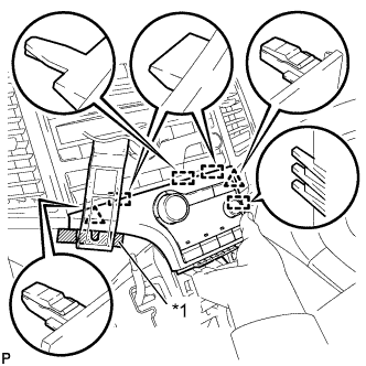
Text in Illustration *1 Protective Tape Apply protective tape to the area shown in the illustration.
-
Using a moulding remover, disengage the 2 clips and 4 guides as shown in the illustration.
-
Disconnect the connector and remove the air conditioning control assembly.
-
-
REMOVE FRONT DOOR SCUFF PLATE LH
-
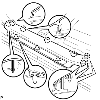
Disengage the 3 clips, 7 claws and guide, and remove the front door scuff plate LH.
-
-
REMOVE COWL SIDE TRIM SUB-ASSEMBLY LH
-
Remove the clip.
-
Disengage the 2 clips and remove the cowl side trim sub-assembly LH.
-
-
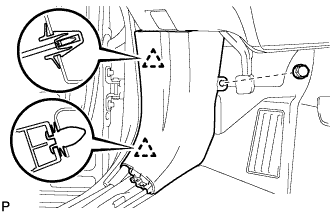
REMOVE LOWER NO. 1 INSTRUMENT PANEL FINISH PANEL
-
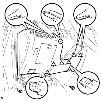
Remove the bolt <C> and screw <E> or <F>.
-
Disengage the claw and 9 clips.
-
Disconnect the connectors.
-
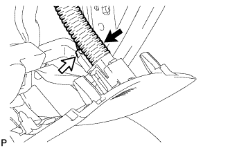
Disconnect the connector and aspirator duct.
-
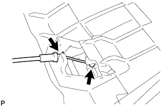
Disconnect the hood lock control cable and remove the lower No. 1 instrument panel finish panel.
-
-
REMOVE FRONT DOOR SCUFF PLATE RH
Tech Tips
Use the same procedure as for the LH side Click here.
-
REMOVE COWL SIDE TRIM SUB-ASSEMBLY RH
Tech Tips
Use the same procedure as for the LH side Click here.
-
REMOVE NO. 2 INSTRUMENT PANEL UNDER COVER SUB-ASSEMBLY
-
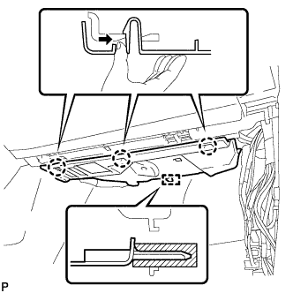
Push the 3 claws in the direction indicated by the arrow to disengage them.
-
Disengage the guide and remove the No. 2 instrument panel under cover sub-assembly.
-
-
REMOVE LOWER INSTRUMENT PANEL SUB-ASSEMBLY
-
Remove the bolt <C> and 4 screws <E> or <F>.
-
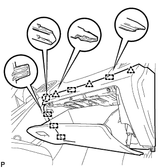
Disengage the claw, 3 clips and 5 guides.
-
Disconnect the connectors and remove the lower instrument panel sub-assembly.
-
-
REMOVE SHIFT LEVER KNOB SUB-ASSEMBLY
-
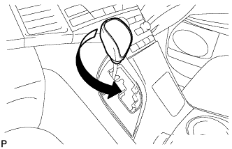
Turn the shift lever knob counterclockwise and remove the shift lever knob sub-assembly.
-
-
REMOVE CONSOLE BOX SUB-ASSEMBLY
-
Remove the 2 screws <E> or <F>.
-
Using a clip remover, remove the clip.
-
Disconnect the connector.
-
Disengage the 2 clamps.
-
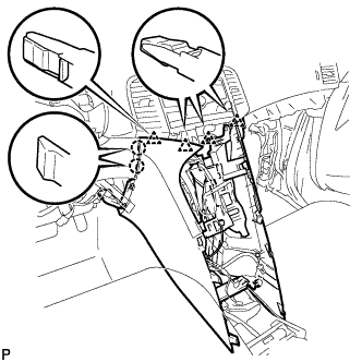
Disengage the 2 claws and 4 clips and remove the console box sub-assembly.
-
-
REMOVE LOWER STEERING COLUMN COVER
-
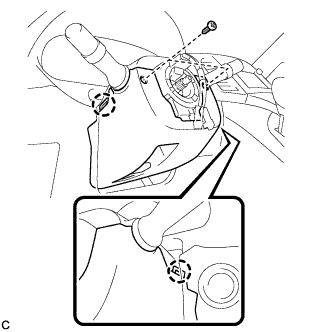
Remove the 2 screws.
-
Push the right and left sides of the lower steering column cover, and disengage the 2 claws to remove the lower steering column cover.
-
-
REMOVE UPPER STEERING COLUMN COVER
-
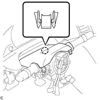
Disengage the claw.
-
Disengage the 4 clips and 2 guides to remove the upper steering column cover.
-
-
REMOVE INSTRUMENT CLUSTER FINISH PANEL
-
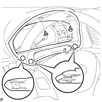
Remove the 2 clips.
-
Disengage the 3 claws and remove the instrument cluster finish panel.
-
-
REMOVE LOWER INSTRUMENT PANEL FINISH PANEL ASSEMBLY
-
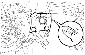
Disengage the 4 claws.
-
Disconnect the connector and remove the lower instrument panel finish panel assembly.
-
-
REMOVE ENGINE SWITCH
-
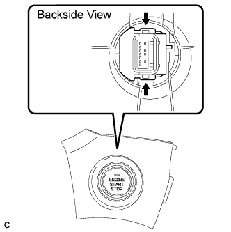
Detach the 2 claws and remove the engine switch.
-