CRUISE CONTROL SYSTEM TERMINALS OF ECM

-
CHECK ECM
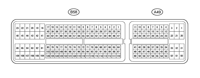
Terminal No. (Symbol) Wiring Color Terminal Description Condition Specified Condition A49-7 (TC) - B58-104 (E1) V - BR Terminal TC of DLC3 Ignition switch ON 11 to 14 V A49-7 (TC) - B58-104 (E1) V - BR Terminal TC of DLC3 Terminals TC and CG of DLC3 connected Below 1 V A49-29 (STP) - B58-104 (E1) G - BR Stop light switch signal Brake pedal depressed 7.5 to 14 V A49-29 (STP) - B58-104 (E1) G - BR Stop light switch signal Brake pedal released Below 1 V A49-39 (ST1-) - B58-104 (E1) V - BR Stop light switch signal Ignition switch ON
Brake pedal depressed
Below 1 V A49-39 (ST1-) - B58-104 (E1) V - BR Stop light switch signal Ignition switch ON
Brake pedal released
7.5 to 14 V A49-40 (CCS) - B58-104 (E1) P - BR Cruise control main switch signal Ignition switch ON 11 to 14 V A49-40 (CCS) - B58-104 (E1) P - BR Cruise control main switch signal CANCEL switch on 6.6 to 10.1 V A49-40 (CCS) - B58-104 (E1) P - BR Cruise control main switch signal - SET switch on 4.5 to 7.1 V A49-40 (CCS) - B58-104 (E1) P - BR Cruise control main switch signal + RES switch on 2.3 to 4.0 V A49-40 (CCS) - B58-104 (E1) P - BR Cruise control main switch signal MAIN switch on Below 1 V