INTAKE MANIFOLD REMOVAL

-
DISCHARGE FUEL SYSTEM PRESSURE
Tech Tips
-
DISCONNECT CABLE FROM NEGATIVE BATTERY TERMINAL
CAUTION:
When disconnecting the cable, some systems need to be initialized after the cable is reconnected Click here.
-
REMOVE THROTTLE BODY ASSEMBLY
-
Remove the throttle body assembly Click here.
-
-
REMOVE VACUUM SWITCHING VALVE ASSEMBLY (for ACIS)
-
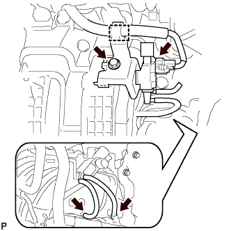
Disconnect the 2 vacuum hoses, 2 union to connector tube hoses, clamp and connector.
-
Remove the bolt and vacuum switching valve assembly (for ACIS).
-
-
DISCONNECT NO. 2 VENTILATION HOSE
-
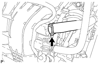
Disconnect the No. 2 ventilation hose from the intake manifold.
-
-
REMOVE UNION TO CONNECTOR TUBE HOSE
-
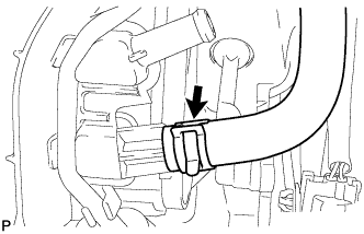
Remove the union to connector tube hose from the intake manifold.
-
-
REMOVE FUEL DELIVERY PIPE SUB-ASSEMBLY
-
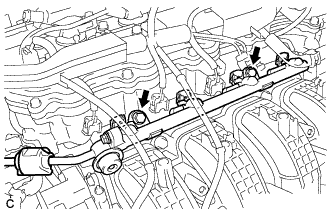
Remove the 2 bolts, and then remove the fuel delivery pipe together with the 4 fuel injectors.
Note
Be careful not to drop the fuel injectors when removing the fuel delivery pipe.
-
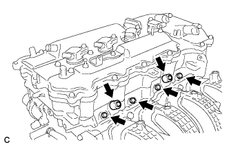
Remove the 2 fuel delivery spacers from the cylinder head.
-
Remove the 4 injector vibration insulators from the cylinder head.
-
-
REMOVE INTAKE MANIFOLD
-
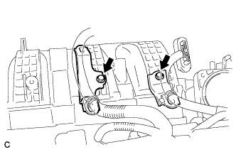
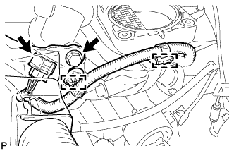
Remove the 2 bolts and 2 wire harness brackets.
-
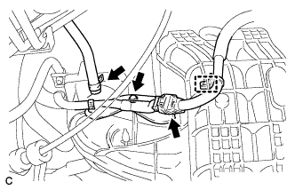
Disconnect the fuel vapor feed hose, clamp and connector.
-
Remove the bolt and wire harness bracket.
-
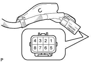
Apply battery voltage to the terminals of the connector to close the tumble control valves.
Standard Tester Connection Specified Condition Positive (+) battery voltage applied to terminal 8 (M-), and negative (-) battery voltage applied to terminal 4 (M+) Open → Closed Note
-
If this procedure is not performed, the tumble control valves may be damaged when the intake manifold is removed.
-
Apply battery voltage for 1 to 3 seconds.
-
If battery voltage is applied for more than 3 seconds, the actuator may be damaged.
-
Do not allow the lead wires to contact the other terminals.
-
-
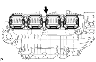
Remove the bolt.
-
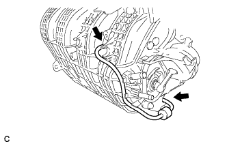
Detach the 2 clamps from the intake manifold and bracket.
-
Disconnect the intake air control valve actuator connector.
-
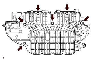
Remove the 6 bolts and intake manifold.
Note
The tumble control valves may be damaged if they are not closed before installing the intake manifold.
Tech Tips
Connect the battery to the terminals of the actuator to operate the motor and close the valves Click here.
-
Remove the intake manifold gasket from the intake manifold.
-
-
REMOVE CHECK VALVE
-
Disconnect the 2 vacuum hoses from the intake manifold and remove the check valve.
-
-
REMOVE WIRING HARNESS CLAMP BRACKET
-
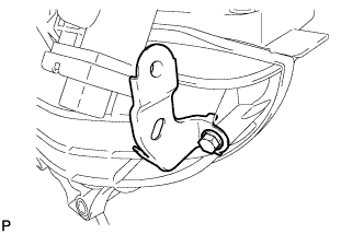
Remove the bolt and wiring harness clamp bracket.
-
-
REMOVE ENGINE MOUNTING DAMPER
-
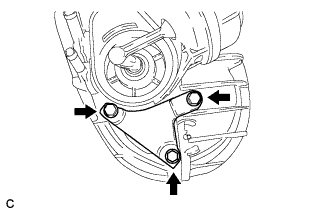
Remove the 3 bolts and engine mounting damper.
-