FUEL SENDER GAUGE ASSEMBLY INSTALLATION

-
INSTALL FUEL SENDER GAUGE ASSEMBLY
-
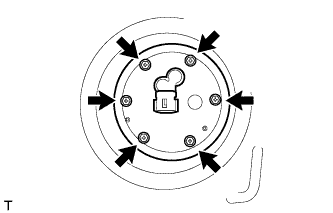
Install the fuel sender gauge assembly to the fuel tank with the 6 bolts.
- Torque:
- 3.5 N*m { 36 kgf*cm, 31 in.*lbf }
Note
Be careful not to bend the arm of the fuel sender gauge assembly.
-
-
INSTALL REAR NO. 2 FLOOR SERVICE HOLE COVER
-
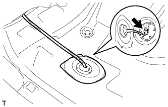
Connect the fuel sender gauge connector.
-
Install the rear No. 2 floor service hole cover with new butyl tape.
-
-
INSTALL FUEL SENDER GAUGE
-
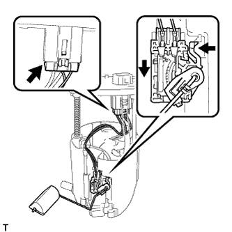
Install the fuel sender gauge by sliding it downward.
Note
Make sure that the fuel sender gauge arm does not bend.
-
Connect the connector of the fuel sender gauge.
Note
Do not damage the wire harness.
-
-
INSTALL FUEL SUCTION TUBE ASSEMBLY WITH PUMP AND GAUGE
-
Install the fuel suction tube assembly with pump and gauge Click here.
-
-
CONNECT CABLE TO NEGATIVE BATTERY TERMINAL
Note
When disconnecting the cable, some systems need to be initialized after the cable is reconnected Click here.
-
INSPECT FOR FUEL LEAK
-
Check fuel pump operation.
-
Connect the GTS to the DLC3.
-
Turn the ignition switch to ON and turn the GTS on.
Note
Do not start the engine.
-
Enter the following menus: Powertrain / Engine / Active Test / Control the Fuel Pump / Speed.
-
Check for pressure in the fuel inlet tube from the fuel line. Check that the sound of fuel flowing from the fuel tank can be heard. If no sound can be heard, check the integration relay, fuel pump, ECM and wiring connectors.
-
-
Inspect for fuel leaks.
-
Check that there are no fuel leaks from the fuel system after doing any maintenance or repairs. If there is a fuel leak, repair or replace parts as necessary.
-
-
Turn the ignition switch off.
-
Disconnect the GTS from the DLC3.
-