FUEL TANK INSTALLATION

-
INSTALL NO. 1 FUEL TANK CUSHION
-
Install 8 new No. 1 fuel tank cushions to the fuel tank assembly.
-
-
INSTALL FUEL MAIN TUBE SUPPORT
-
Install the fuel main tube support to the fuel tank assembly with the bolt.
- Torque:
- 5.4 N*m { 55 kgf*cm, 48 in.*lbf }
-
-
INSTALL FUEL TANK MAIN TUBE SUB-ASSEMBLY
-
Install the fuel tank main tube sub-assembly to the fuel main tube support.
-
-
INSTALL FUEL TANK TO FILLER PIPE HOSE
-
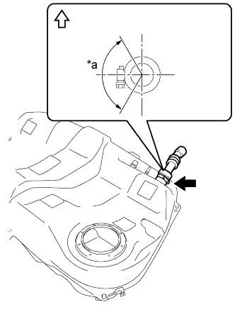
Text in Illustration *a 120° 
Upper Install the fuel tank to filler pipe hose to the fuel tank assembly and tighten the clamp to secure it.
Tech Tips
Make sure the clamp bolt is within the area shown in the illustration.
-
-
INSTALL FUEL TANK BREATHER TUBE SUB-ASSEMBLY
-
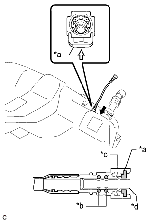
Text in Illustration *a Retainer *b O-ring *c Fuel Tube Connector *d Fuel Pipe 
Push Push in Install the fuel tank breather tube sub-assembly to the fuel tank assembly.
Note
Check if there is any damage or foreign matter on the connecting parts of the fuel lines.
-
Align the fuel tube connector with the fuel pipe, and push them together until the fuel tube connector makes a "click" sound. If it is difficult to push the fuel pipe into the fuel tube connector, apply a small amount of clean engine oil to the tip of the fuel pipe and reinsert it.
-
Connect the fuel lines and push in the retainer. Check that the fuel pipe and fuel tube connector are securely connected by pulling on them.
-
-
-
INSTALL FUEL TANK VENT HOSE SUB-ASSEMBLY
-
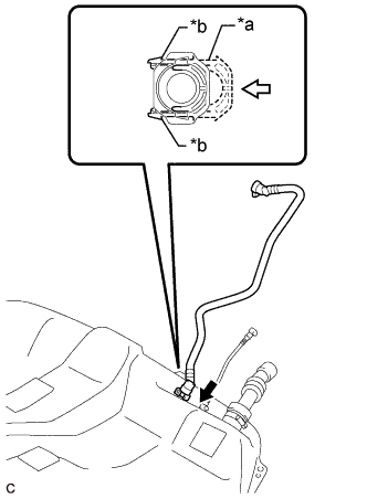
Text in Illustration *a Retainer *b Claw Push Push in Push the fuel tank vent hose sub-assembly onto the fuel tank assembly and push in the retainer to engage the 2 claws.
Note
-
Check that there are no scratches or foreign matter around the connecting parts of the fuel tank vent hose sub-assembly and fuel tank assembly before performing this work.
-
After connecting the fuel tank vent hose sub-assembly, check that the fuel tank vent hose sub-assembly is securely connected by pulling on it.
-
-
-
INSTALL FUEL TANK ASSEMBLY
-
Install the 4 clip nuts to the fuel tank assembly.
-
Install the 2 fuel tank band sub-assemblies with the 2 straight pins as shown in the illustration.
-
Set the fuel tank assembly on an engine lifter.
-
Using the engine lifter, slowly raise the fuel tank assembly, and then install the fuel tank assembly with the 2 fuel tank band sub-assemblies with the 2 bolts.
- Torque:
- 45 N*m { 459 kgf*cm, 33 ft.*lbf }
Note
-
Do not drop the fuel tank assembly.
-
When installing the fuel tank assembly, tilt it slightly to prevent it from interfering with the other surrounding parts.
-
Text in Illustration *a 120° Upper Connect the fuel tank to filler pipe hose and tighten the clamp to secure it.
-
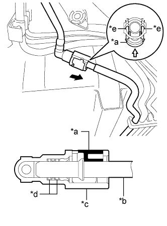
Text in Illustration *a Retainer *b O-ring *c Fuel Tube Connector *d Fuel Pipe Push Push in Connect the fuel tank breather tube sub-assembly.
Note
Check if there is any damage or foreign matter on the connecting parts of the fuel lines.
-
Align the fuel tube connector with the fuel pipe, and push them together until the fuel tube connector makes a "click" sound. If it is difficult to push the fuel pipe into the fuel tube connector, apply a small amount of clean engine oil to the tip of the fuel pipe and reinsert it.
-
Connect the fuel lines and push in the retainer. Check that the fuel pipe and fuel tube connector are securely connected by pulling on them.
-
-
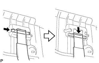
Engage the 2 clamps to connect the fuel tank vent hose sub-assembly.
-
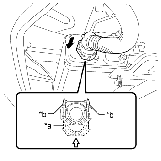
Text in Illustration *a Retainer *b Claw Push Push in Push the fuel tank vent hose sub-assembly onto the charcoal canister assembly and push in the retainer to engage the 2 claws.
Note
-
Check that there are no scratches or foreign matter around the connecting parts of the fuel tank vent hose sub-assembly and charcoal canister assembly before performing this work.
-
After connecting the fuel tank vent hose sub-assembly, check that the fuel tank vent hose sub-assembly is securely connected by pulling on it.
-
-
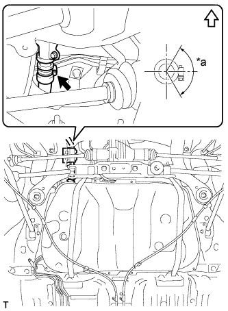
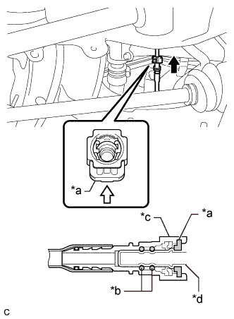
Text in Illustration *a Retainer *b Fuel Pipe *c Fuel Tube Connector *d O-ring *e Claw Push Push in Connect the fuel tank main tube sub-assembly.
Note
Check if there is any damage or foreign matter on the connecting parts of the fuel lines.
-
Align the fuel tube connector with the fuel pipe, and push them together until the fuel tube connector makes a "click" sound. If it is difficult to push the fuel pipe into the fuel tube connector, apply a small amount of clean engine oil to the tip of the fuel pipe and reinsert it.
-
Connect the fuel lines and push in the retainer to engage the 2 claws. Check that the fuel pipe and fuel tube connector are securely connected by pulling on them.
-
-
-
INSTALL NO. 3 PARKING BRAKE CABLE ASSEMBLY
-
Install the No. 3 parking brake cable assembly with the bolt and nut.
- Torque:
- 6.0 N*m { 61 kgf*cm, 53 in.*lbf }
-
-
INSTALL NO. 2 PARKING BRAKE CABLE ASSEMBLY
-
Install the No. 2 parking brake cable assembly with the bolt and nut.
- Torque:
- 6.0 N*m { 61 kgf*cm, 53 in.*lbf }
-
-
INSTALL NO. 1 FUEL TANK PROTECTOR SUB-ASSEMBLY
-
Install the No. 1 fuel tank protector sub-assembly with the 4 bolts.
- Torque:
- 5.4 N*m { 55 kgf*cm, 48 in.*lbf }
-
-
INSTALL FRONT FLOOR BRACE LH
-
Install the front floor brace LH with the bolt and 2 nuts.
- Torque:
- 56 N*m { 571 kgf*cm, 41 ft.*lbf }
-
-
INSTALL FRONT FLOOR BRACE RH
-
Install the front floor brace RH with the bolt and 2 nuts.
- Torque:
- 56 N*m { 571 kgf*cm, 41 ft.*lbf }
-
-
INSTALL ELECTRO MAGNETIC CONTROL COUPLING SUB-ASSEMBLY (for AWD)
-
Using a scraper and wire brush, remove the seal packing from the rear differential carrier assembly and electro magnetic control coupling sub-assembly.
Note
Do not scratch the installation area.
-
Using a non-residue solvent, remove grease and oil from the contact surfaces of the rear differential carrier assembly and the electro magnetic control coupling sub-assembly.
-
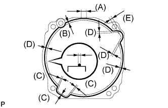
Apply seal packing to the areas indicated in the illustration of the electro magnetic control coupling sub-assembly.
Seal packing Toyota Genuine Seal Packing 1281, Three Bond 1281 or equivalent Note
-
Stop applying seal packing after allowing it to overlap with the beginning of the bead by at least 10 mm (0.394 in.) within range (A) in the illustration.
-
Make sure that the clearance from the center of the bead is within 1 mm (0.0394 in.).
-
Install the electro magnetic control coupling sub-assembly within 10 minutes after applying seal packing.
-
Apply seal packing in a continuous bead 2 to 3 mm (0.0787 to 0.118 in.) in diameter.
Tech Tips
-
(B) : 1.0 mm (0.0394 in.)
-
(C) : 2.0 mm (0.0787 in.)
-
(D) : 3.0 mm (0.118 in.)
-
(E) : 5.0 mm (0.197 in.)
-
-
Apply hypoid gear oil to the splines of the rear drive pinion.
-
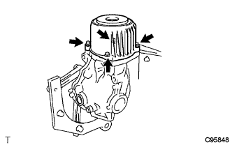
Install the electro magnetic control coupling sub-assembly with the 4 bolts.
- Torque:
- 20 N*m { 200 kgf*cm, 14 ft.*lbf }
Note
-
Do not damage the diaphragm oil seal.
-
Do not damage the contact surface of the electro magnetic control coupling sub-assembly.
-
-
INSTALL PROPELLER WITH CENTER BEARING SHAFT ASSEMBLY (for AWD)
-
INSTALL CENTER EXHAUST PIPE ASSEMBLY
-
ADD FUEL
-
INSTALL FUEL SENDER GAUGE ASSEMBLY
-
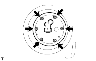
Install the fuel sender gauge assembly to the fuel tank with the 6 bolts.
- Torque:
- 3.5 N*m { 36 kgf*cm, 31 in.*lbf }
Note
Be careful not to bend the arm of the fuel sender gauge assembly.
-
-
INSTALL REAR NO. 2 FLOOR SERVICE HOLE COVER
-
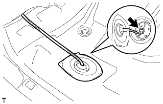
Connect the fuel sender gauge connector.
-
Install the rear No. 2 floor service hole cover with new butyl tape.
-
-
INSTALL FUEL SUCTION TUBE ASSEMBLY WITH PUMP AND GAUGE
-
CONNECT CABLE TO NEGATIVE BATTERY TERMINAL
Note
When disconnecting the cable, some systems need to be initialized after the cable is reconnected Click here.
-
INSPECT FOR EXHAUST GAS LEAK