FUEL INJECTOR INSTALLATION

-
INSTALL FUEL INJECTOR ASSEMBLY
-
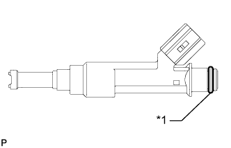
Text in Illustration *1 O-ring Apply a light coat of gasoline or spindle oil to new O-rings, and then install one onto each fuel injector assembly.
-
Apply a light coat of gasoline or spindle oil to the contact surfaces of the new O-ring on each fuel injector assembly.
-
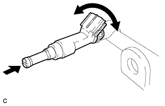
While turning the fuel injector assembly left and right, install it onto the fuel delivery pipe sub-assembly.
Note
Make sure that the O-ring is not cracked or jammed when installing the injector Click here.
-
Check that the fuel injector rotates smoothly. If the fuel injector does not rotate, replace the O-ring.
-
-
INSTALL FUEL DELIVERY PIPE SUB-ASSEMBLY
-
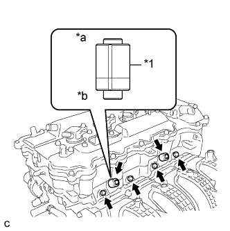
Text in Illustration *1 Fuel Delivery Spacer *a Fuel Delivery Pipe Side *b Cylinder Head Side Install 4 new injector vibration insulators to the cylinder head.
-
Install the 2 fuel delivery spacers onto the cylinder head.
Tech Tips
Install the fuel delivery spacer so that the longer protrusion is on the cylinder head side.
-
Install the fuel delivery pipe sub-assembly together with the 4 fuel injectors to the cylinder head, and then temporarily install the 2 bolts.
Note
Be careful not to drop the fuel injectors when installing the fuel delivery pipe sub-assembly.
-
Tighten the 2 bolts to the specified torque.
- Torque:
- 21 N*m { 214 kgf*cm, 15 ft.*lbf }
Note
-
Do not drop the fuel injectors when installing the fuel delivery pipe sub-assembly.
-
Check that the fuel injector assemblies rotate smoothly after installing the fuel delivery pipe sub-assembly.
-
-
CONNECT WIRE HARNESS
-
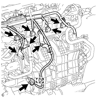
Install the 2 wire harness brackets with the 2 bolts.
- Torque:
- 8.4 N*m { 85 kgf*cm, 74 in.*lbf }
-
Connect the 2 connectors.
-
Connect the 4 fuel injector connectors.
-
Engage the clamp to connect the wire harness.
-
-
INSTALL VACUUM SWITCHING VALVE ASSEMBLY (for ACIS)
-
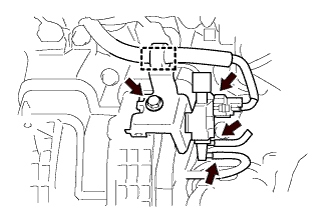
Install the vacuum switching valve assembly (for ACIS) with the bolt.
- Torque:
- 9.0 N*m { 92 kgf*cm, 80 in.*lbf }
-
Connect the 2 vacuum hoses, clamp and connector.
-
-
CONNECT FUEL TUBE SUB-ASSEMBLY
-
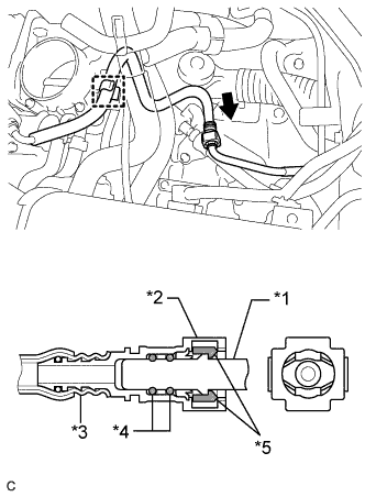
Text in Illustration *1 Fuel Pipe *2 Fuel Tube Connector *3 Nylon Tube *4 O-ring *5 Retainer 
Push Push the fuel tube connector to the fuel pipe until the fuel tube connector makes a "click" sound.
Note
-
Before connecting the fuel tube connector and fuel pipe, check that there is no damage or foreign matter on the connecting part of the fuel pipe.
-
After connecting the fuel tube connector and fuel pipe, check that they are securely connected by trying to pull them apart.
-
-
Install the No. 1 fuel pipe clamp.
-
Install the fuel tube sub-assembly to the fuel hose clamp.
-
-
INSTALL AIR CLEANER CAP SUB-ASSEMBLY
-
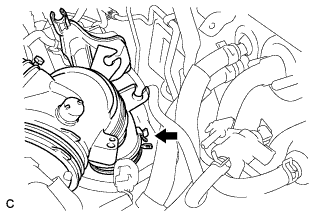
Connect the air-cleaner cap sub-assembly to the throttle body assembly and lock the hose band.
-
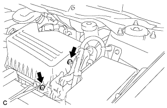
Install the air cleaner cap sub-assembly with the 2 bolts.
- Torque:
- 5.0 N*m { 51 kgf*cm, 44 in.*lbf }
-
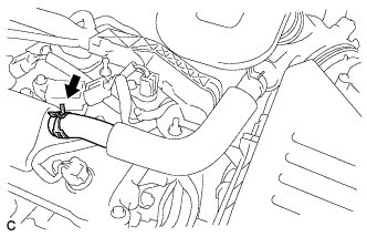
Connect the ventilation hose to the cylinder head cover.
-
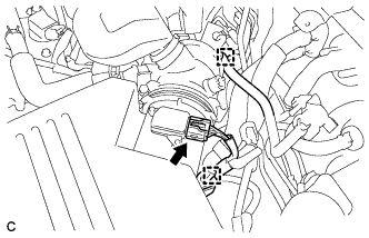
Connect the mass air flow meter connector and install the wire harness clamp to the air cleaner cap.
-
Install the hose to the hose clamp.
-
-
INSTALL NO. 1 VACUUM SWITCHING VALVE ASSEMBLY
-
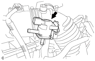
Install the No. 1 vacuum switching valve assembly.
-
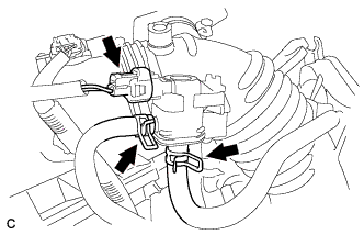
Connect the connector and 2 fuel vapor feed hoses.
-
-
INSTALL NO. 1 ENGINE COVER SUB-ASSEMBLY
-
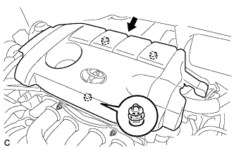
Fit the 3 retainers and install the No. 1 engine cover sub-assembly.
-
-
INSTALL OUTER COWL TOP PANEL
-
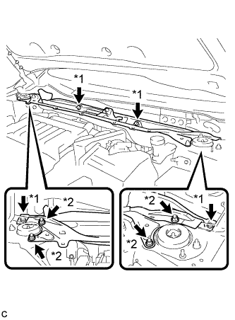
Text in Illustration *1 Bolt *2 Nut Install the outer cowl top panel with the 4 bolts and 4 nuts.
- Torque:
- Nut
- 85 N*m { 866 kgf*cm, 63 ft.*lbf }
- Bolt
- 8.8 N*m { 90 kgf*cm, 78 in.*lbf }
-
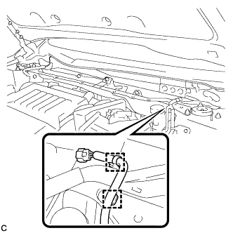
Engage the 2 wire harness clamps to the outer cowl top panel.
-
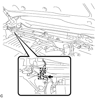
Engage the 2 wire harness clamps to the outer cowl top panel and connect the connector (w/ Windshield Deicer).
-
-
INSTALL WINDSHIELD WIPER MOTOR AND LINK ASSEMBLY
-
Install the windshield wiper motor and link assembly Click here.
-
-
CONNECT CABLE TO NEGATIVE BATTERY TERMINAL
Note
When disconnecting the cable, some systems need to be initialized after the cable is reconnected Click here.
-
INSPECT FOR FUEL LEAK
-
Check fuel pump operation.
-
Connect the GTS to the DLC3.
-
Turn the ignition switch to ON and turn the GTS on.
Note
Do not start the engine.
-
Enter the following menus: Powertrain / Engine / Active Test / Control the Fuel Pump / Speed.
-
Check for pressure in the fuel inlet tube from the fuel line. Check that the sound of fuel flowing from the fuel tank can be heard. If no sound can be heard, check the integration relay, fuel pump, ECM and wiring connectors.
-
-
Inspect for fuel leaks.
-
Check that there are no fuel leaks from the fuel system after doing any maintenance or repairs. If there is a fuel leak, repair or replace parts as necessary.
-
-
Turn the ignition switch off.
-
Disconnect the GTS from the DLC3.
-