FUEL INJECTOR INSPECTION

-
INSPECT FUEL INJECTOR ASSEMBLY
-
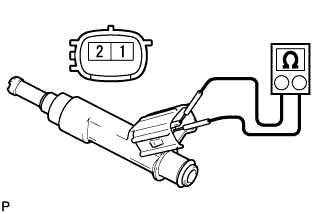
Measure the resistance according to the value(s) in the table below.
Standard Resistance Tester Connection Condition Specified Condition 1 - 2 20°C (68°F) 11.6 to 12.4 Ω If the result is not as specified, replace the fuel injector assembly.
-
Inspect the injector injection.
CAUTION:
Keep the injector away from sparks during the test.
-
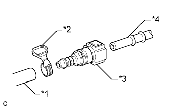
Text in Illustration *1 SST
(Hose)
*2 SST
(Hose Band)
*3 SST
(Fuel Tube Connector)
*4 Fuel Pipe (Vehicle Side) Connect SST (fuel tube connector) to SST (hose) with SST (hose band), and then connect them to the fuel pipe (vehicle side).
- SST
- 09268-31014 ( 09268-41500, 09268-41700, 95336-08070 )
-
Install a new O-ring to the fuel injector assembly.
-
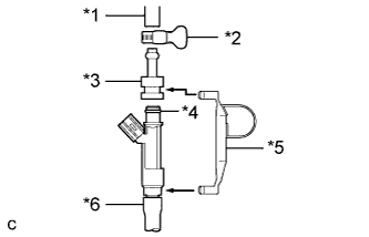
Text in Illustration *1 SST
(Hose)
*2 SST
(Hose Band)
*3 SST
(Adapter)
*4 O-ring *5 SST
(Clamp)
*6 Vinyl Tube Connect SST (adapter and hose) to the fuel injector assembly, and hold the fuel injector assembly and union with SST (clamp).
- SST
- 09268-31014 ( 09268-41110, 09268-41300, 09268-41700, 95336-08070 )
-
Install a vinyl tube onto the fuel injector assembly.
CAUTION:
Install a suitable vinyl tube onto the injector to contain any gasoline spray.
-
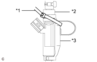
Text in Illustration *1 SST
(Tie Band)
*2 SST
(Adapter)
*3 SST
(Clamp)
Tie the clamp and adapter together with SST (tie band) as shown in the illustration.
- SST
- 09268-31014 ( 09268-41110, 09268-41300, 09268-41800 )
-
Put the fuel injector assembly into a graduated cylinder.
-
Operate the fuel pump Click here.
-
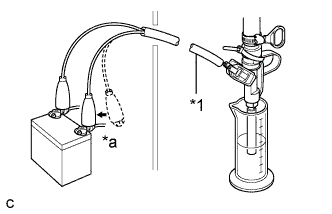
Text in Illustration *1 SST
(Wire)
*a Connect Connect SST (wire) to the fuel injector assembly and the battery for 15 seconds, and measure the injection volume with the graduated cylinder. Test each fuel injector assembly 2 or 3 times.
- SST
- 09842-30080
Standard Injection Volume Tester Connection Condition Specified Condition Positive terminal - Ground terminal Per 15 seconds 88 to 106 cc (5.4 to 6.5 cu. in.) Standard difference between each fuel injector assembly 18 cc (1.1 cu. in.) or less If the result is not as specified, replace the fuel injector assembly.
-
-
Check for fuel drop.
-
In the condition above, disconnect the tester probes of SST (wire) from the battery and check for fuel drop from the fuel injector assembly.
Standard fuel drop 1 drop or less per 20 minutes If fuel drop is not as specified, replace the fuel injector assembly.
-
-