VACUUM SWITCHING VALVE (for ACIS) REMOVAL

-
REMOVE FRONT WIPER ARM HEAD CAP
-
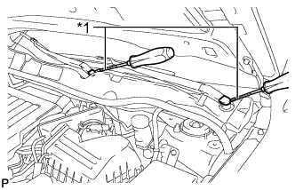
Text in Illustration *1 Protective Tape Using a screwdriver, remove the 2 front wiper arm head caps as shown in the illustration.
Tech Tips
Tape the screwdriver tip before use.
-
-
REMOVE FRONT WIPER ARM AND BLADE ASSEMBLY LH
-
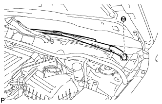
Remove the nut and the front wiper arm and blade assembly LH.
-
-
REMOVE FRONT WIPER ARM AND BLADE ASSEMBLY RH
-
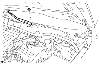
Remove the nut and the front wiper arm and blade assembly RH.
-
-
REMOVE FRONT FENDER TO COWL SIDE SEAL LH
-
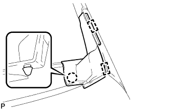
Disengage the claw and 2 guides and remove the front fender to cowl side seal LH.
-
-
REMOVE FRONT FENDER TO COWL SIDE SEAL RH
Tech Tips
Use the same procedure for the RH side and LH side.
-
REMOVE COWL TOP VENTILATOR LOUVER SUB-ASSEMBLY
-
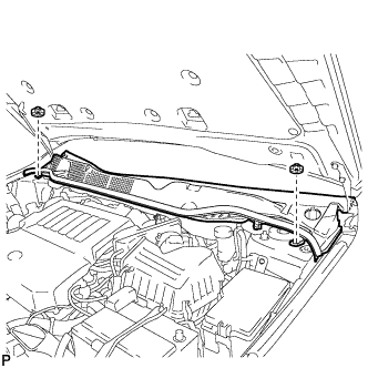
Using a clip remover, remove the 2 clips.
-
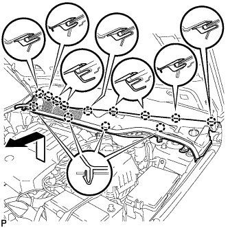
Disengage the 13 claws and pull out the cowl top ventilator louver sub-assembly as shown in the illustration.
-
-
REMOVE WINDSHIELD WIPER MOTOR AND LINK ASSEMBLY
-
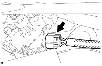
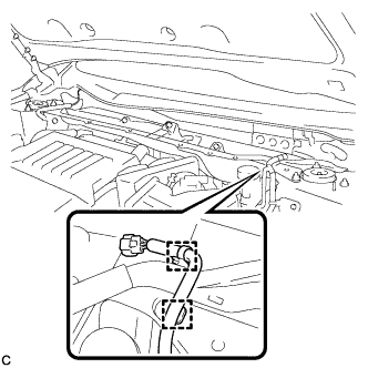
Disconnect the connector.
-
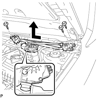
Remove the 3 bolts and the windshield wiper motor and link assembly as shown in the illustration.
-
-
REMOVE OUTER COWL TOP PANEL
-
Disengage the 2 clamps and separate the wiper wire harness from the outer cowl top panel sub-assembly.
-
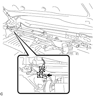
Disengage the 2 clamps and connector, and separate the wire harness from the outer cowl top panel sub-assembly (w/ Windshield Deicer).
-
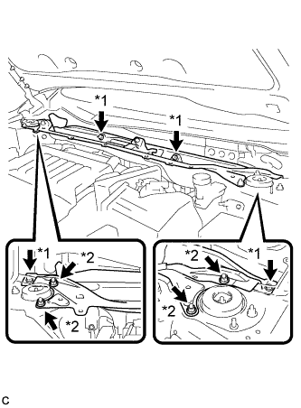
Text in Illustration *1 Bolt *2 Nut Remove the 4 bolts, 4 nuts and outer cowl top panel sub-assembly.
-
-
REMOVE NO. 1 ENGINE COVER SUB-ASSEMBLY
-
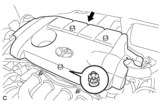
Lift the rear of the No. 1 engine cover sub-assembly to detach the cover from the 2 pins, and then lift the front of the No. 1 engine cover sub-assembly to detach the cover from the pin and remove the No. 1 engine cover sub-assembly.
Note
Attempting to disengage both front and rear clips at the same time may cause the No. 1 engine cover sub-assembly to break.
-
-
REMOVE VACUUM SWITCHING VALVE ASSEMBLY (for ACIS)
-
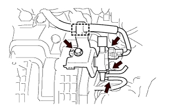
Disconnect the 2 vacuum hoses, clamp and connector.
-
Remove the bolt and vacuum switching valve assembly (for ACIS).
-