ENGINE ASSEMBLY INSTALLATION

-
INSTALL ENGINE HANGERS
-
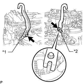
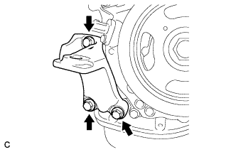
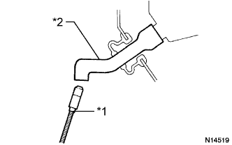
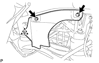
Text in Illustration *1 No. 1 Engine Hanger *2 No. 2 Engine Hanger Install the 2 engine hangers with the 2 bolts as shown in the illustration.
Item Part No. No. 1 engine hanger 12281-36020 No. 2 engine hanger 12282-36020 Bolt 91552-81040, 91552-81025 - Torque:
- 43 N*m { 438 kgf*cm, 32 ft.*lbf }
Tech Tips
Fit the fork part of the No. 2 engine hanger onto the rib of the cylinder head.
-
Attach the engine sling device and hang the engine with the chain block.
-
-
REMOVE ENGINE STAND
-
Remove the engine stand.
-
-
INSTALL ENGINE WIRE
-
Install the engine wire.
-
-
INSTALL DRIVE PLATE AND RING GEAR SUB-ASSEMBLY
-
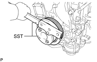
Using SST, hold the crankshaft.
- SST
- 09213-54015
- 09330-00021
Tech Tips
SST (Crankshaft pulley holding tool) Fixing bolt part No. : 91551-80650(2 pcs)
-
Clean the bolts and their installation holes.
-
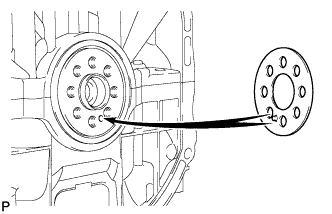
Install the front drive plate spacer.
Tech Tips
Align the pin of the front drive plate spacer with the pin hole of the crankshaft.
-
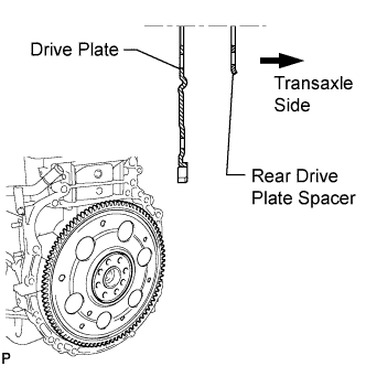
Install the drive plate and rear drive plate spacer to the crankshaft.
-
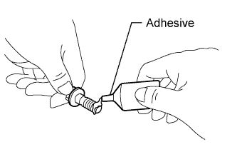
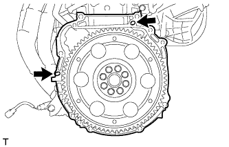
Apply a few drops of adhesive to 2 or 3 threads of the bolt end.
Adhesive Toyota Genuine Adhesive 1324, Three Bond 1324 or equivalent -
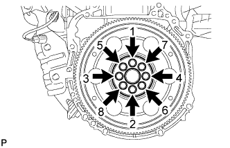
Install and uniformly tighten the 8 bolts in the sequence shown in the illustration.
- Torque:
- 98 N*m { 999 kgf*cm, 72 ft.*lbf }
Note
Do not strike or damage the drive plate installation bolts. Be sure to handle them carefully.
-
-
INSTALL REAR ENGINE MOUNTING BRACKET (for AWD)
-
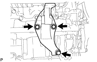
Install the rear engine mounting bracket with the 3 bolts.
- Torque:
- 64 N*m { 650 kgf*cm, 47 ft.*lbf }
-
-
INSTALL DRIVE SHAFT BEARING BRACKET (for 2WD)
-
Install the drive shaft bearing bracket with the 3 bolts.
- Torque:
- 64 N*m { 649 kgf*cm, 47 ft.*lbf }
-
-
INSTALL ENGINE MOUNTING BRACKET RH
-
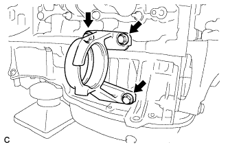
Install the engine mounting bracket RH with the 3 bolts.
- Torque:
- 54 N*m { 551 kgf*cm, 40 ft.*lbf }
-
-
INSTALL AUTOMATIC TRANSAXLE ASSEMBLY (for 2WD)
-
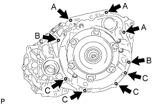
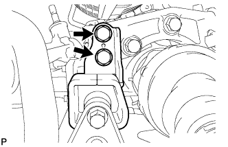
Confirm that the 2 knock pins are on the transaxle contact surface of the engine block before the transaxle installation.
-
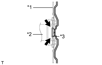
Text in Illustration *1 Drive Plate *2 Crankshaft *3 Torque Converter Assembly Centerpiece Apply clutch spline grease to the circumference of the crankshaft contact surface with the torque converter assembly centerpiece.
Clutch spline grease Toyota Genuine Clutch Splice Grease or equivalent Maximum spread About 1 g (0.0353 oz.) -
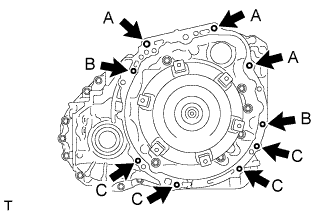
While keeping the engine and automatic transaxle assembly horizontal, align the knock pins with the holes in the automatic transaxle assembly and install the 9 bolts shown in the illustration.
- Torque:
- Bolt A
- 64 N*m { 653 kgf*cm, 47 ft.*lbf }
- Bolt B
- 46 N*m { 469 kgf*cm, 34 ft.*lbf }
- Bolt C
- 44 N*m { 449 kgf*cm, 32 ft.*lbf }
Note
-
Do not forcibly pry on the automatic transaxle assembly.
-
Check that the torque converter assembly rotates.
Tech Tips
Bolt length:
-
Bolt A: 55 mm (2.17 in.)
-
Bolt B: 50 mm (1.97 in.)
-
Bolt C: 32 or 33 mm (1.26 or 1.30 in.)
-
-
INSTALL AUTOMATIC TRANSAXLE ASSEMBLY (for AWD)
-
Confirm that the 2 knock pins are on the transaxle contact surface of the engine block before the transaxle installation.
-
Text in Illustration *1 Drive Plate *2 Crankshaft *3 Torque Converter Assembly Centerpiece Apply clutch spline grease to the circumference of the crankshaft contact surface with the torque converter assembly centerpiece.
Clutch splice grease Toyota Genuine Clutch Spline Grease or equivalent Maximum spread About 1 g (0.0353 oz.) -
While keeping the engine and automatic transaxle assembly horizontal, align the knock pins with each the holes in the automatic transaxle assembly and install the 9 bolts shown in the illustration.
- Torque:
- Bolt A
- 64 N*m { 653 kgf*cm, 47 ft.*lbf }
- Bolt B
- 46 N*m { 469 kgf*cm, 34 ft.*lbf }
- Bolt C
- 44 N*m { 449 kgf*cm, 32 ft.*lbf }
Note
-
Do not forcibly pry on the automatic transaxle assembly.
-
Check that the torque converter assembly rotates.
Tech Tips
Bolt length:
-
Bolt A: 55 mm (2.17 in.)
-
Bolt B: 50 mm (1.97 in.)
-
Bolt C: 32 or 33 mm (1.26 or 1.30 in.)
-
-
INSTALL TRANSFER STIFFENER PLATE RH (for AWD)
-
Temporarily install the transfer stiffener plate RH.
-
Tighten the transfer stiffener plate RH with the 4 bolts to the transfer and rear engine mounting bracket.
- Torque:
- Bolt A
- 34 N*m { 347 kgf*cm, 25 ft.*lbf }
- Bolt B
- 78 N*m { 795 kgf*cm, 58 ft.*lbf }
-
-
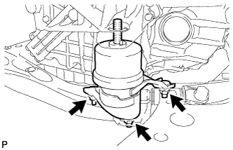
TEMPORARILY TIGHTEN FRONT ENGINE MOUNTING INSULATOR ASSEMBLY
-
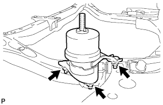
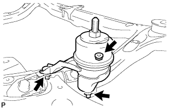
Temporarily install the front engine mounting insulator assembly with the 3 nuts.
Tech Tips
Perform this procedure only when replacement of the engine mounting insulator is necessary.
-
-
TEMPORARILY TIGHTEN ENGINE MOUNTING INSULATOR LH
-
Temporarily install the engine mounting insulator LH with the 3 nuts.
Tech Tips
Perform this procedure only when replacement of the engine mounting insulator is necessary.
-
-
TEMPORARILY TIGHTEN ENGINE MOUNTING INSULATOR RH
-
Temporarily install the engine mounting insulator RH with the 3 nuts.
Tech Tips
Perform this procedure only when replacement of the engine mounting insulator is necessary.
-
-
TEMPORARILY TIGHTEN REAR ENGINE MOUNTING INSULATOR ASSEMBLY (for AWD)
-
Temporarily install the rear engine mounting insulator with the 2 nuts.
Tech Tips
Perform this procedure only when replacement of the engine mounting insulator is necessary.
-
-
INSTALL FRONT FRAME ASSEMBLY
-
Set the engine assembly with transaxle to the front frame assembly.
-
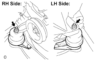
Install the engine mounting insulators RH and LH with the 2 nuts.
- Torque:
- 95 N*m { 968 kgf*cm, 70 ft.*lbf }
-
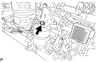
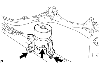
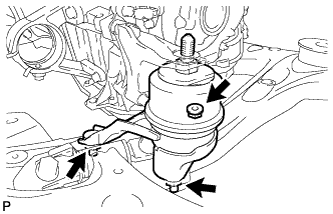
Install the front engine mounting insulator with the bolt.
- Torque:
- 87 N*m { 887 kgf*cm, 64 ft.*lbf }
-
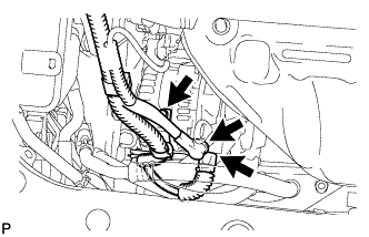
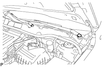
Connect the 2 clamps with the engine wire.
-
-
INSTALL REAR ENGINE MOUNTING INSULATOR ASSEMBLY (for AWD)
-
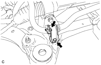
Install the rear engine mounting insulator assembly with the 2 bolts to the engine mounting bracket.
- Torque:
- 75 N*m { 764 kgf*cm, 55 ft.*lbf }
-
-
FULLY TIGHTEN FRONT ENGINE MOUNTING INSULATOR ASSEMBLY
-
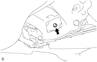
Fully tighten the front engine mounting insulator with the 3 nuts.
- Torque:
- 52 N*m { 530 kgf*cm, 38 ft.*lbf }
-
Install the hole plug.
Tech Tips
Perform this procedure only when replacement of the engine mounting insulator is necessary.
-
-
FULLY TIGHTEN ENGINE MOUNTING INSULATOR LH
-
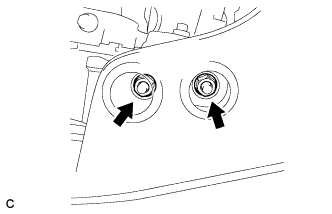
Fully tighten the engine mounting insulator LH with the 3 nuts.
- Torque:
- 87 N*m { 887 kgf*cm, 64 ft.*lbf }
-
Install the 2 hole plugs.
Tech Tips
Perform this procedure only when replacement of the engine mounting insulator is necessary.
-
-
FULLY TIGHTEN ENGINE MOUNTING INSULATOR RH
-
Fully tighten the engine mounting insulator RH with the 3 nuts.
- Torque:
- 87 N*m { 887 kgf*cm, 64 ft.*lbf }
-
Install the 2 hole plugs.
Tech Tips
Perform this procedure only when replacement of the engine mounting insulator is necessary.
-
-
FULLY TIGHTEN REAR ENGINE MOUNTING INSULATOR ASSEMBLY (for AWD)
-
Fully tighten the rear engine mounting insulator with the 2 nuts.
- Torque:
- 52 N*m { 530 kgf*cm, 38 ft.*lbf }
-
Install the 2 hole plugs.
Tech Tips
Perform this procedure only when replacement of the engine mounting insulator is necessary.
-
-
INSTALL STEERING LINK ASSEMBLY (for AWD)
-
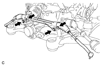
Install the steering link assembly with the 2 bolts and 2 nuts.
- Torque:
- 70 N*m { 713 kgf*cm, 51 ft.*lbf }
Note
-
Make sure to tighten the bolts starting from the left side of the vehicle.
-
Because the nut has its own stopper, do not turn the nut. Tighten the bolt with the nut secured.
-
-
INSTALL FRONT STABILIZER BAR (for AWD)
-
Install the front stabilizer bar.
-
-
INSTALL NO. 1 FRONT STABILIZER BRACKET LH (for AWD)
-
Install the front No. 1 stabilizer bracket LH to the front frame assembly with the 2 bolts.
- Torque:
- 29 N*m { 296 kgf*cm, 21 ft.*lbf }
-
-
INSTALL NO. 1 FRONT STABILIZER BRACKET RH (for AWD)
Tech Tips
Use the same procedure described for the LH side.
-
INSTALL STARTER ASSEMBLY
-
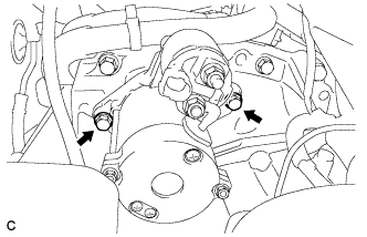
Install the starter with the 2 bolts.
- Torque:
- 37 N*m { 377 kgf*cm, 27 ft.*lbf }
-
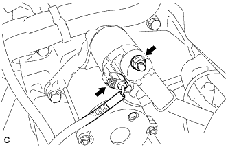
Connect the starter connector.
-
Install the terminal nut and cover the nut with the cap.
- Torque:
- 9.8 N*m { 100 kgf*cm, 87 in.*lbf }
-
-
INSTALL COMPRESSOR ASSEMBLY WITH PULLEY
-
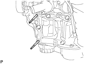
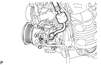
Using an E8 "TORX" socket wrench, install the 2 stud bolts.
- Torque:
- 10 N*m { 102 kgf*cm, 7 ft.*lbf }
-
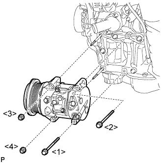
Install the compressor assembly with pulley with the 2 bolts and 2 nuts.
- Torque:
- 25 N*m { 255 kgf*cm, 18 ft.*lbf }
Note
Tighten the bolts and nuts in the order shown in the illustration to install the compressor assembly with pulley.
-
-
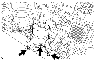
INSTALL GENERATOR ASSEMBLY
-
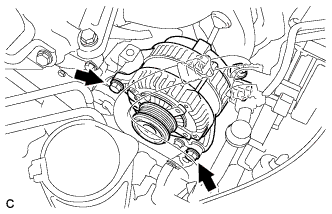
Install the generator with the 2 bolts.
- Torque:
- 52 N*m { 530 kgf*cm, 38 ft.*lbf }
-
Install the wire harness clamp bracket with the bolt.
- Torque:
- 10 N*m { 102 kgf*cm, 7 ft.*lbf }
-
Connect the generator wire with the nut.
- Torque:
- 9.8 N*m { 100 kgf*cm, 87 in.*lbf }
-
Install the terminal cap.
-
Connect the generator connector.
-
-
INSTALL V-RIBBED BELT
-
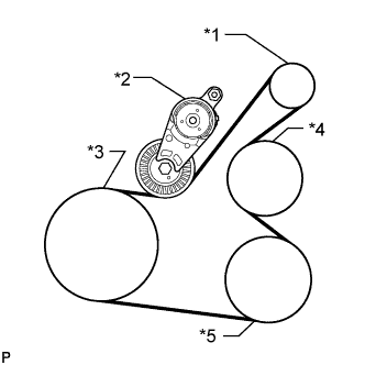
Text in Illustration *1 Generator *2 Tensioner *3 Crankshaft *4 Water Pump *5 Cooler Compressor Set the V-ribbed belt onto each part as shown in the illustration except the water pump pulley.
-
Loosen the V-ribbed belt by turning the belt tensioner clockwise.
-
Set the V-ribbed belt onto the water pump pulley.
Note
Make sure that the belt is attached to each pulley. In particular, make sure that the belt is securely fitted into the grooves of the crankshaft pulley.
-
-
REMOVE ENGINE HANGERS
-
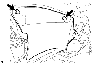
Text in Illustration *1 No. 1 Engine Hanger *2 No. 2 Engine Hanger Remove the 2 bolts and No. 1 and No. 2 engine hangers.
-
-
INSTALL ENGINE ASSEMBLY WITH TRANSAXLE
-
Set the engine assembly with transaxle on the engine lifter.
-
Install the engine assembly to the vehicle.
-
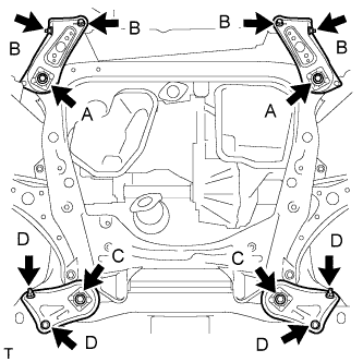
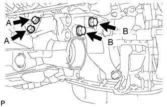
Install the frame side rail plates RH and LH with the 4 bolts and 2 nuts.
- Torque:
- A
- 85 N*m { 866 kgf*cm, 62 ft.*lbf }
- B
- 32 N*m { 326 kgf*cm, 24 ft.*lbf }
-
Install the front suspension member rear braces RH and LH with the 4 bolts and 2 nuts.
- Torque:
- C
- 85 N*m { 866 kgf*cm, 62 ft.*lbf }
- D
- 32 N*m { 326 kgf*cm, 24 ft.*lbf }
-
-
INSTALL DRIVE PLATE AND TORQUE CONVERTER ASSEMBLY SETTING BOLT
-
Using SST, hold the crankshaft pulley.
- SST
- 09213-54015
- 09330-00021
Tech Tips
SST (Crankshaft pulley holding tool) Fixing bolt part No. : 91551-80650(2 pcs)
-
Apply a few drops of adhesive to the first 2 or 3 threads of the 6 drive plate and torque converter assembly setting bolts.
Adhesive Toyota Genuine Adhesive 1324, Three Bond 1324 or equivalent -
Install the 6 drive plate and torque converter assembly setting bolts.
- Torque:
- 41 N*m { 418 kgf*cm, 30 ft.*lbf }
Note
Install the black colored bolt first, and then the 5 silver colored bolts.
-
-
INSTALL FLYWHEEL HOUSING UNDER COVER
-
Install the flywheel housing under cover.
-
-
INSTALL FRONT FLOOR BRACE
-
Install the front floor brace with the 4 nuts.
- Torque:
- 11 N*m { 112 kgf*cm, 8 ft.*lbf }
-
-
INSTALL FRONT DRIVE SHAFT HOLE SNAP RING (for LH Side)
-
Install a new front drive shaft hole snap ring.
-
-
INSTALL FRONT DRIVE SHAFT ASSEMBLY LH
-
Align the splines of the shaft and install the drive shaft assembly LH using a brass bar and a hammer.
Note
-
Set the shaft snap ring with the opening facing down.
-
Be careful not to damage the drive shaft dust cover, boot or oil seal.
-
Move the drive shaft assembly while keeping it level.
-
-
-
INSTALL FRONT DRIVE SHAFT ASSEMBLY RH (for 2WD)
-
Install the front drive shaft assembly RH.
-
Install the bearing bracket hole snap ring and a new bolt.
- Torque:
- 32 N*m { 330 kgf*cm, 24 ft.*lbf }
Note
-
Do not damage the boot or oil seal.
-
Move the drive shaft assembly while keeping it level.
-
-
INSTALL FRONT DRIVE SHAFT ASSEMBLY RH (for AWD)
-
Install the front drive shaft assembly RH.
-
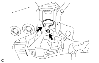
Install the bearing bracket hole snap ring and a new bolt.
- Torque:
- 32 N*m { 330 kgf*cm, 24 ft.*lbf }
Note
-
Do not damage the boot or oil seal.
-
Move the drive shaft assembly while keeping it level.
-
-
INSTALL FRONT AXLE ASSEMBLY LH
-
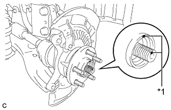
Text in Illustration *1 Matchmark Align the matchmarks and install the front drive shaft assembly to the front axle hub sub-assembly.
-
-
INSTALL FRONT AXLE ASSEMBLY RH
Tech Tips
Use the same procedure described for the LH side.
-
INSTALL FRONT LOWER SUSPENSION ARM LH
-
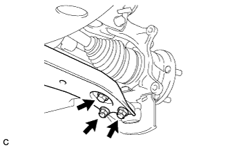
Install the front lower suspension arm to the front lower ball joint with the bolt and 2 nuts.
- Torque:
- 92 N*m { 938 kgf*cm, 68 ft.*lbf }
-
-
INSTALL FRONT LOWER SUSPENSION ARM RH
Tech Tips
Use the same procedure described for the LH side.
-
INSTALL FRONT STABILIZER LINK ASSEMBLY LH
-
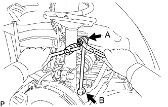
Install the front stabilizer link assembly LH with the 2 nuts.
- Torque:
- Nut A
- 130 N*m { 1326 kgf*cm, 96 ft.*lbf }
- Nut B
- 74 N*m { 755 kgf*cm, 55 ft.*lbf }
Tech Tips
If the ball joint turns together with the nut, use a hexagon wrench (6 mm) to hold the stud bolt.
-
-
INSTALL FRONT STABILIZER LINK ASSEMBLY RH
Tech Tips
Use the same procedure described for the LH side.
-
INSTALL TIE ROD ASSEMBLY LH
-
Connect the tie rod assembly LH to the steering knuckle with the nut.
- Torque:
- 49 N*m { 500 kgf*cm, 36 ft.*lbf }
-
Install a new cotter pin.
Note
Further tighten the nut up to 60° if the holes for the cotter pin are not aligned.
-
-
INSTALL TIE ROD ASSEMBLY RH
Tech Tips
Use the same procedure described for the LH side.
-
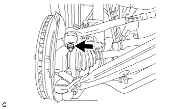
INSTALL FRONT SPEED SENSOR LH
-
Install the front speed sensor and front flexible hose with the bolt.
- Torque:
- 19 N*m { 194 kgf*cm, 14 ft.*lbf }
Note
-
Do not twist the front speed sensor when installing it.
-
First install the speed sensor harness bracket, and then install the flexible hose bracket.
-
Install the front speed sensor to the steering knuckle with the bolt.
- Torque:
- 8.5 N*m { 87 kgf*cm, 75 in.*lbf }
Note
-
Prevent foreign matter from attaching to the front speed sensor tip.
-
Firmly insert the front speed sensor body into the steering knuckle before tightening the bolt.
-
After installing the front speed sensor to the steering knuckle, make sure that there is no clearance between the front speed sensor stay and steering knuckle. Also make sure that no foreign matter is stuck between the parts.
-
To prevent interference between the front speed sensor and magnetic rotor, do not rotate the front speed sensor body during or after the insertion of the front speed sensor body to the steering knuckle.
-
-
INSTALL FRONT SPEED SENSOR RH
Tech Tips
Use the same procedure described for the LH side.
-
INSTALL FRONT AXLE SHAFT NUT LH
-
Clean the threaded parts on the front drive shaft and a new front axle shaft nut using a non-residue solvent.
Tech Tips
-
Be sure to perform this work for a new drive shaft.
-
Keep the threaded parts free of oil and foreign matter.
-
-

Install the new front axle shaft nut.
- Torque:
- 294 N*m { 2998 kgf*cm, 217 ft.*lbf }
-
Using a chisel and hammer, stake the front axle shaft nut.
-
-
INSTALL FRONT AXLE SHAFT NUT RH
Tech Tips
Use the same procedure described for the LH side.
-
INSTALL STEERING INTERMEDIATE SHAFT SUB-ASSEMBLY
-
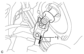
Text in Illustration *1 Matchmark Align the matchmarks on the steering intermediate shaft assembly and steering link assembly.
-
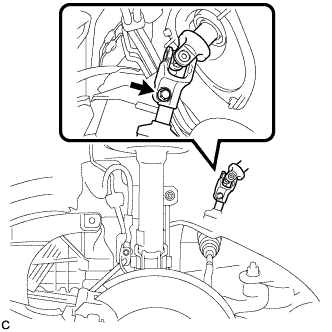
Install the bolt.
- Torque:
- 35 N*m { 357 kgf*cm, 26 ft.*lbf }
-
-
TEMPORARILY TIGHTEN PROPELLER WITH CENTER BEARING SHAFT ASSEMBLY
-
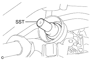
Remove SST from the transfer.
- SST
- 09325-20010
-
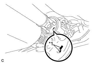
Install the propeller with center bearing shaft assembly.
Note
-
Be careful not to damage the oil seal.
-
Be careful not to damage the universal joint boot when installing the propeller shaft.
-
-
Text in Illustration *1 Matchmark Align the matchmarks on the rear propeller shaft and electromagnetic control coupling assembly and install the 4 nuts and 4 washers temporarily.
Note
Do not allow grease to adhere to be bolts or washers.
-
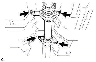
Temporarily install the propeller with center bearing shaft assembly with the 4 bolts, 2 No. 1 center support bearing washers and 2 No. 2 center support bearing washers.
Note
-
Reuse the washers.
-
Do not allow grease to adhere to be bolts or washers.
-
-
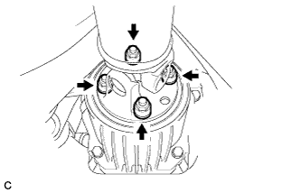
Fully tighten the 4 nuts.
- Torque:
- 37 N*m { 379 kgf*cm, 27 ft.*lbf }
-
-
FULLY TIGHTEN PROPELLER WITH CENTER BEARING SHAFT ASSEMBLY
- SST
- 09370-50010
-
Remove the piece of cloth or equivalent from the universal joint.
-
Depress the brake pedal and hold it.
-
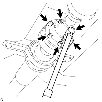
Using a hexagon wrench (6 mm), tighten the 6 bolts.
- Torque:
- 26 N*m { 265 kgf*cm, 19 ft.*lbf }
-
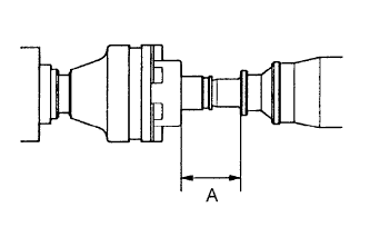
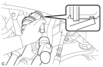
With the vehicle unloaded, adjust the dimension between the rear side of the cover and shaft as shown in the illustration.
Length A 65.5 to 70.5 mm (2.579 to 2.776 in.) -
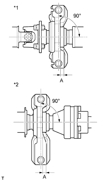
Text in Illustration *1 No. 1 Center Support Bearing Assembly *2 No. 2 Center Support Bearing Assembly With the vehicle unloaded, adjust the front and rear dimensions between the edge surface of the center support bearing and the edge surface of the cushion respectively as shown in the illustration, and then tighten the bolts.
Length A 11.5 to 13.5 mm (0.453 to 0.532 in.) -
Check that the center line of the bracket is at a right angle to the shaft axial direction.
-
Fully tighten the 4 bolts.
- Torque:
- 37 N*m { 375 kgf*cm, 27 ft.*lbf }
-
INSTALL CENTER EXHAUST PIPE ASSEMBLY (for AWD)
-
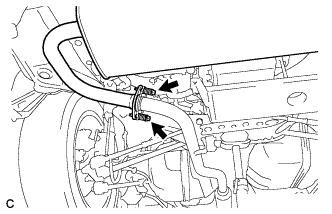
Install a new gasket to the center exhaust pipe assembly.
-
Connect the center exhaust pipe assembly to the 2 exhaust pipe supports.
-
Install the center exhaust pipe assembly with the 2 bolts.
- Torque:
- 43 N*m { 438 kgf*cm, 32 ft.*lbf }
-
-
INSTALL TAIL EXHAUST PIPE ASSEMBLY (for AWD)
-
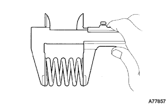
Using a vernier caliper, measure the free length of the compression springs.
Minimum length 38.5 mm (1.52 in.) If the free length is less than the minimum, replace the compression spring.
-
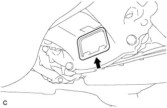
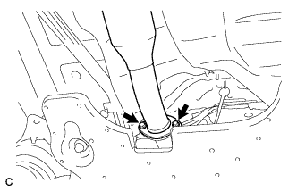
Fully insert a new gasket to the center exhaust pipe assembly.
-
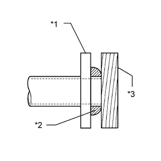
Text in Illustration *1 Center Exhaust Pipe Assembly *2 Gasket *3 Wooden Block Using a plastic hammer and wooden block, tap in the new gasket until its surface is flush with the center exhaust pipe assembly.
Note
-
Be sure to install the gasket in the correct direction.
-
Do not reuse the gasket.
-
Do not damage the gasket.
-
Do not push in the gasket by using the exhaust pipe when connecting it.
-
-
Connect the tail exhaust pipe assembly to the 4 exhaust pipe supports.
-
Install the tail exhaust pipe assembly with the 2 bolts and 2 compression springs.
- Torque:
- 43 N*m { 438 kgf*cm, 32 ft.*lbf }
-
-
INSTALL FRONT EXHAUST PIPE ASSEMBLY
-
Using a vernier caliper, measure the free length of the compression springs.
Minimum length 41.5 mm (1.64 in.) If the free length is less than the minimum, replace the compression spring.
-
Fully insert a new gasket to the exhaust manifold converter sub-assembly.
-

Text in Illustration *1 Exhaust Manifold Converter Sub-assembly *2 Gasket *3 Wooden Block Using a plastic hammer and wooden block, tap in the new gasket until its surface is flush with the exhaust manifold converter sub-assembly.
Note
-
Be sure to install the gasket in the correct direction.
-
Do not reuse the gasket.
-
Do not damage the gasket.
-
Do not push in the gasket by using the exhaust pipe when connecting it.
-
-
Install the front exhaust pipe assembly with the 2 bolts and 2 compression springs.
- Torque:
- 43 N*m { 438 kgf*cm, 32 ft.*lbf }
-
-
CONNECT COOLER REFRIGERANT DISCHARGE HOSE
-
Remove the attached vinyl tape from the hose.
-
Apply sufficient compressor oil to a new O-ring and the fitting surface of the compressor assembly with pulley.
Compressor oil ND-OIL 8 or equivalent -
Install the O-ring onto the discharge hose.
Note
Keep the O-ring and O-ring fitting surfaces free from dirt or any foreign objects.
-
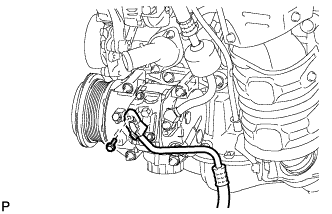
Install the cooler refrigerant discharge hose onto the compressor assembly with pulley with the bolt.
- Torque:
- 9.8 N*m { 100 kgf*cm, 87 in.*lbf }
-
Using pliers, grip the claws of the clip and slide the clip to install the No. 2 radiator hose.
-
Engage each clamp.
-
Connect each connector.
-
-
CONNECT SUCTION HOSE SUB-ASSEMBLY
-
Remove the attached vinyl tape from the hose.
-
Apply sufficient compressor oil to a new O-ring and the fitting surface of the compressor assembly with pulley.
Compressor oil ND-OIL 8 or equivalent -
Install the O-ring onto the suction hose sub-assembly.
Note
Keep the O-ring and O-ring fitting surfaces free from dirt or any foreign objects.
-
Install the suction hose sub-assembly onto the compressor assembly with pulley with the bolt.
- Torque:
- 9.8 N*m { 100 kgf*cm, 87 in.*lbf }
-
-
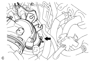
CONNECT UNION TO CHECK VALVE HOSE
-
Using pliers, grip the claws of the clip and slide the clip to connect the union to check valve hose to the intake air surge tank assembly.
-
-
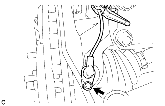
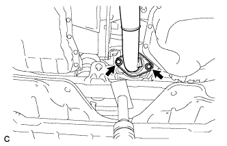
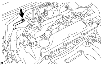
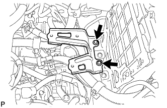
INSTALL ENGINE MOVING CONTROL ROD
-
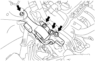
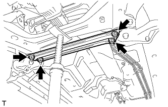
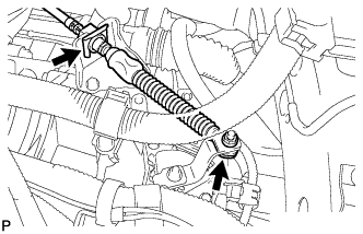
Temporarily install the engine moving control rod with the 4 bolts.
-
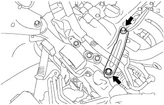
Temporarily install the No. 2 engine mounting stay with the 2 bolts
-
Tighten the 6 bolts.
- Torque:
- 38 N*m { 387 kgf*cm, 28 ft.*lbf }
-
-
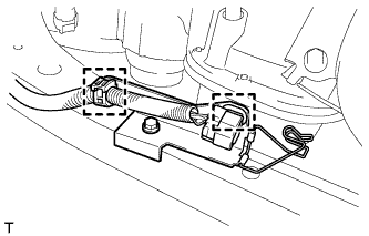
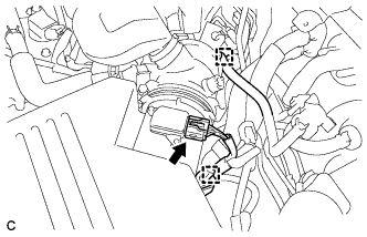
CONNECT ENGINE WIRE
-
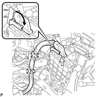
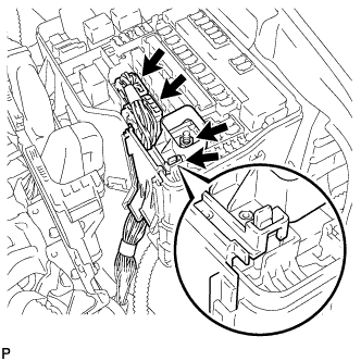
Connect the connector to the ECM with the lock lever.
-
Connect the engine wire with the 2 clamps.
-
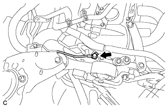
Install the ground cable with the bolt.
- Torque:
- 5.5 N*m { 56 kgf*cm, 49 in.*lbf }
-
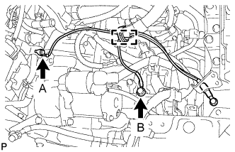
Install the ground cable with the 2 bolts.
- Torque:
- Bolt A
- 8.0 N*m { 82 kgf*cm, 71 in.*lbf }
- Bolt B
- 12 N*m { 122 kgf*cm, 9 ft.*lbf }
-
Connect the ground cable clamp.
-
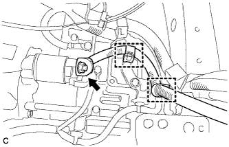
Connect the positive (+) cable with the nut and 2 clamps.
- Torque:
- 9.8 N*m { 100 kgf*cm, 87 in.*lbf }
-
Install the ground cable with the bolt.
- Torque:
- 8.4 N*m { 86 kgf*cm, 74 in.*lbf }
-
Connect the 2 engine wire clamps.
-
Connect the engine wire to the engine room relay block. Then, install it with the nut and 2 connectors.
- Torque:
- 8.0 N*m { 85 kgf*cm, 74 in.*lbf }
-
Install the No. 1 relay block cover.
-
-
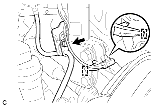
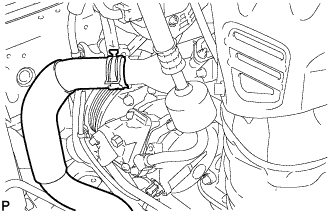
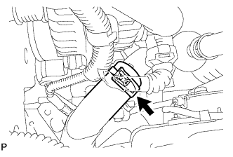
CONNECT TRANSMISSION CONTROL CABLE ASSEMBLY
-
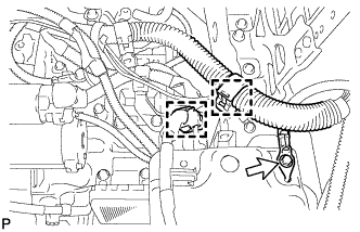
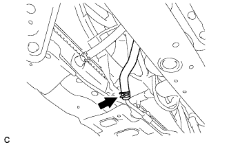
Connect the transmission control cable assembly to the control shaft lever with a new clip and the nut.
- Torque:
- 13 N*m { 130 kgf*cm, 9 ft.*lbf }
Note
Before connecting the transmission control cable assembly, check that the park/neutral position switch and the shift lever are in N.
-
-
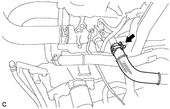
CONNECT OUTLET NO. 1 OIL COOLER HOSE
-
Connect the outlet No. 1 oil cooler hose.
-
-
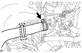
CONNECT INLET NO. 1 OIL COOLER HOSE
-
Connect the inlet No. 1 oil cooler hose.
-
-
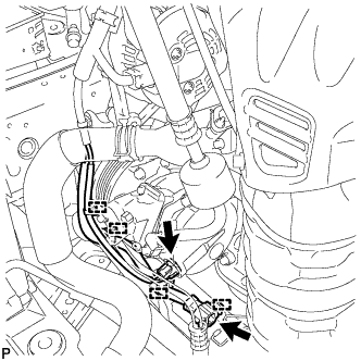
CONNECT FUEL TUBE SUB-ASSEMBLY
-
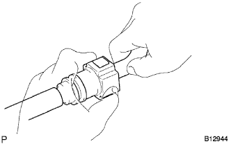
Push in the fuel tube connector to the fuel pipe until the fuel tube makes a "click" sound.
Note
-
Check for damage or dirt and foreign objects on the connecting part of the pipe.
-
Check if the pipe and the connector are securely connected by trying to pull them apart.
-
-
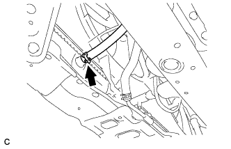
Install the No. 1 fuel pipe clamp.
-
-
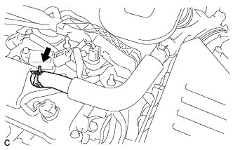
CONNECT OUTLET HEATER WATER HOSE
-
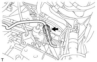
Connect the outlet heater water hose.
-
-
CONNECT INLET HEATER WATER HOSE
-
Connect the inlet heater water hose.
-
-
CONNECT NO. 1 RADIATOR HOSE
-
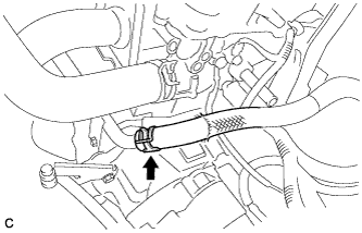
Connect the No. 1 radiator hose.
-
Connect the wire harness clamp.
-
-
CONNECT NO. 2 RADIATOR HOSE
-
Connect the No. 2 radiator outlet hose.
-
-
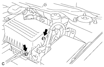
INSTALL AIR CLEANER BRACKET
-
Install the air cleaner bracket with the 2 bolts.
- Torque:
- 7.8 N*m { 80 kgf*cm, 69 in.*lbf }
-
-
INSTALL AIR CLEANER CASE SUB-ASSEMBLY
-
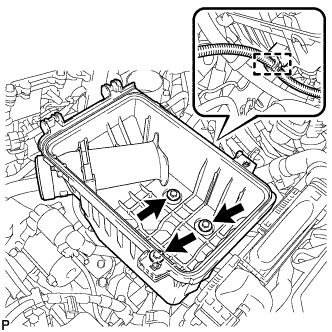
Install the air cleaner case sub-assembly with the 3 bolts.
- Torque:
- 5.0 N*m { 51 kgf*cm, 44 in.*lbf }
-
connect the wire harness clamp.
-
-
INSTALL AIR CLEANER FILTER ELEMENT SUB-ASSEMBLY
-
Install the air cleaner filter element sub-assembly.
-
-
INSTALL AIR CLEANER CAP SUB-ASSEMBLY
-
Connect the air-cleaner cap sub-assembly to the throttle body assembly and lock the hose band.
-
Install the air cleaner cap sub-assembly with the 2 bolts.
- Torque:
- 5.0 N*m { 51 kgf*cm, 44 in.*lbf }
-
Connect the ventilation hose to the cylinder head cover.
-
Connect the mass air flow meter connector and install the wire harness clamp to the air cleaner cap.
-
Install the hose to the hose clamp.
-
-
INSTALL INLET AIR CLEANER ASSEMBLY
-
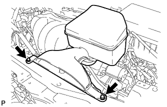
Install the inlet air cleaner assembly with the 2 bolts.
- Torque:
- 5.0 N*m { 51 kgf*cm, 44 in.*lbf }
-
-
INSTALL BATTERY
-
Install the battery tray and battery.
-
Install the battery clamp with the bolt and nut.
- Torque:
- Bolt A
- 9.0 N*m { 92 kgf*cm, 80 in.*lbf }
- Nut B
- 3.5 N*m { 36 kgf*cm, 31 in.*lbf }
-
Install the positive (+) battery terminal with the nut.
- Torque:
- 6.4 N*m { 65 kgf*cm, 57 in.*lbf }
-
-
INSTALL OUTER COWL TOP PANEL SUB-ASSEMBLY
-
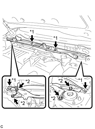
Text in Illustration *1 Bolt *2 Nut Install the outer cowl top panel with the 4 bolts and 4 nuts.
- Torque:
- Nut
- 85 N*m { 866 kgf*cm, 63 ft.*lbf }
- Bolt
- 8.8 N*m { 90 kgf*cm, 78 in.*lbf }
-
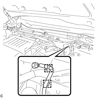
Engage the 2 wire harness clamps to the outer cowl top panel.
-
Engage the 2 wire harness clamps to the outer cowl top panel and connect the connector (w/ Windshield Deicer).
-
-
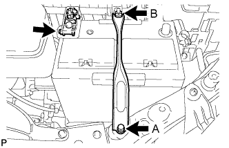
INSTALL WINDSHIELD WIPER MOTOR AND LINK ASSEMBLY
-
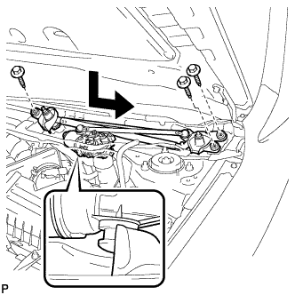
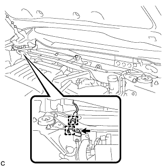
Install the windshield wiper motor and link assembly with the 3 bolts as shown in the illustration.
- Torque:
- 7.0 N*m { 71 kgf*cm, 62 in.*lbf }
-
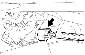
Connect the connector.
-
-
INSTALL COWL TOP VENTILATOR LOUVER SUB-ASSEMBLY
-
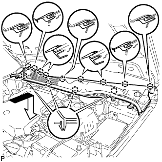
Engage the 13 claws and install the cowl top ventilator louver sub-assembly as shown in the illustration.
-
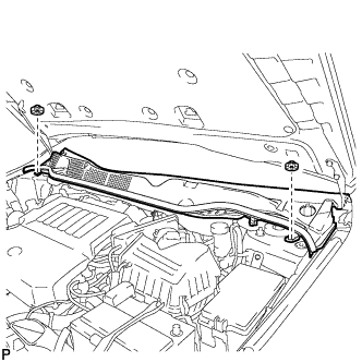
Install the 2 clips.
-
-
INSTALL FRONT FENDER TO COWL SIDE SEAL LH
-
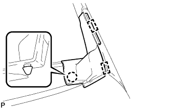
Engage the claw and 2 guides to install the front fender to cowl side seal LH.
-
-
INSTALL FRONT FENDER TO COWL SIDE SEAL RH
Tech Tips
Use the same procedure for the RH side and LH side.
-
INSTALL FRONT WIPER ARM AND BLADE ASSEMBLY LH
-
When reusing the front wiper arm and blade assembly LH:
-
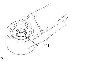
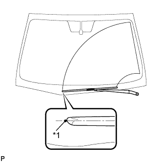
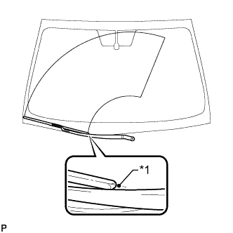
Text in Illustration *1 Wiper Arm Serration Clean the wiper arm serrations.
-
-
When reusing the windshield wiper link assembly:
-
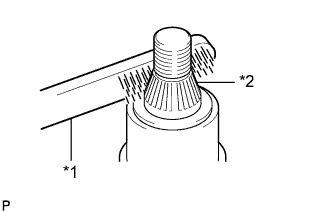
Text in Illustration *1 Wire Brush *2 Wiper Pivot Serration Clean the wiper pivot serrations with a wire brush.
-
-
Text in Illustration *1 Ceramic Notch Install the front wiper arm and blade assembly LH with the nut to the position shown in the illustration.
- Torque:
- 20 N*m { 204 kgf*cm, 15 ft.*lbf }
-
Operate the front wipers while spraying washer fluid onto the windshield. Make sure that the front wipers function properly and the wipers do not come into contact with the vehicle body.
-
-
INSTALL FRONT WIPER ARM AND BLADE ASSEMBLY RH
-
Operate the wiper and stop the windshield wiper motor at the automatic stop position.
-
When reusing the front wiper arm and blade assembly RH:
-

Text in Illustration *1 Wiper Arm Serration Clean the wiper arm serrations.
-
-
When reusing the windshield wiper link assembly:
-
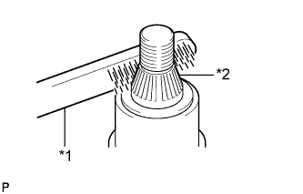
Text in Illustration *1 Wire Brush *2 Wiper Pivot Serration Clean the wiper pivot serrations with a wire brush.
-
-
Text in Illustration *1 Ceramic Notch Install the front wiper arm and blade assembly RH with the nut to the position shown in the illustration.
- Torque:
- 20 N*m { 204 kgf*cm, 15 ft.*lbf }
-
-
INSTALL FRONT WIPER ARM HEAD CAP
-
Install the 2 front wiper arm head caps.
-
-
INSTALL FRONT WHEELS
- Torque:
- 103 N*m { 1050 kgf*cm, 76 ft.*lbf }
-
CONNECT CABLE TO NEGATIVE BATTERY TERMINAL
Note
When disconnecting the cable, some systems need to be initialized after the cable is reconnected Click here.
-
ADD ENGINE OIL
-
Add new engine oil and install the oil filler cap.
Standard Oil Grade Oil Grade Oil Viscosity (SAE)
-
API grade SL "Energy-Conserving", SM "Energy-Conserving", SN "Resource-Conserving" or ILSAC multigrade engine oil
-
0W-20
-
5W-20
-
5W-30
-
10W-30
API grade SL, SM or SN multigrade engine oil
-
15W-40
-
20W-50
Standard Capacity Item Specified Condition Drain and refill (with oil filter change) 4.4 liters (4.6 US qts, 3.9 Imp. qts) Drain and refill (without oil filter change) 4.0 liters (4.2 US qts, 3.5 Imp. qts) Dry fill 5.3 liters (5.6 US qts, 4.7 Imp. qts) -
-
-
ADD ENGINE COOLANT
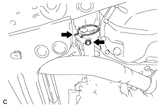
-
Tighten the radiator drain cock plug by hand.
-
Slowly fill the radiator with TOYOTA Super Long Life Coolant (SLLC).
Standard Capacity 7.1 liters (7.5 US qts, 6.2 lmp. qts) Tech Tips
TOYOTA vehicles are filled with TOYOTA SLLC at the factory. In order to avoid damage to the engine cooling system and other technical problems, only use TOYOTA SLLC or similar high quality ethylene glycol based non-silicate, non-amine, non-nitrite, non-borate coolant with long-life hybrid organic acid technology (coolant with long-life hybrid organic acid technology is a combination of low phosphates and organic acids).
Note
Never use water as a substitute for engine coolant.
-
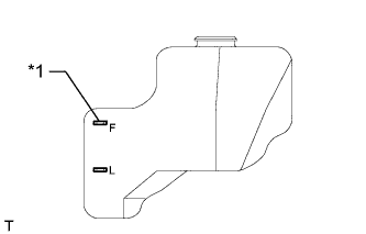
Text in Illustration *1 Full Line Slowly pour coolant into the radiator reservoir tank until it reaches the full line.
-
Squeeze the No. 1 and No. 2 radiator hoses several times by hand, and then check the level of the coolant.
If the coolant level is low, add coolant.
-
Bleed air from the cooling system.
-
Warm up the engine until the thermostat opens. While the thermostat is open, circulate the coolant for several minutes.
Tech Tips
The thermostat open timing can be confirmed by squeezing the No. 2 radiator hose by hand, and sensing vibrations when the engine coolant starts to flow inside the hose.
-
Maintain the engine speed at 2500 to 3000 rpm.
-
Squeeze the inlet and No. 1 and No. 2 radiator hoses several times by hand to bleed air.
CAUTION:
When squeezing the radiator hoses:
-
Wear protective gloves.
-
Be careful as the radiator hoses are hot.
-
Keep your hands away from the cooling fans.
Note
-
Make sure that the radiator reservoir still has some coolant in it.
-
If the coolant temperature gauge indicates an excessive temperature, turn off the engine and let it cool.
-
If there is not enough coolant, the engine may overheat or be seriously damaged.
-
If the radiator reservoir does not have enough coolant, perform the following: 1) stop the engine, 2) wait until the coolant has cooled down, and 3) add coolant until the reservoir is filled to the full line.
-
-
-
Stop the engine and wait until the engine coolant cools down.
-
Add engine coolant to the full line on the radiator reservoir.
-
-
ADD AUTOMATIC TRANSAXLE FLUID (for 2WD)
Tech Tips
-
ADD AUTOMATIC TRANSAXLE FLUID (for AWD)
Tech Tips
-
ADD TRANSFER OIL (for AWD)
-
Remove the No. 1 transfer case plug and gasket.
-
Add oil until the oil level is between 0 and 5 mm (0 and 0.197 in.) from the bottom lip of the case plug hole.
Note
-
When adding transfer oil, make sure the vehicle is level.
-
Add oil slowly, waiting several minutes between each addition.
-
An excessively large or small amount of oil may cause damage.
-
After adding oil, drive the vehicle and recheck the oil level.
Tech Tips
-
Oil grade API GL-5 Viscosity Above 0°F(-18°C): SAE 90 Below 0°F(-18°C): SAE 80W or 80W-90 Capacity 0.8 liters (0.84 US qts, 0.70 lmp.qts)
-
-
After waiting for approximately 5 minutes, recheck the oil level.
-
Install a new gasket onto the No. 1 transfer case plug and then tighten the plug.
- Torque:
- 49 N*m { 500 kgf*cm, 36 ft.*lbf }
-
-
CHARGE REFRIGERANT
-
Perform vacuum purging using a vacuum pump.
-
Charge with refrigerant HFC-134a (R134a).
Standard 450 to 550 g (15.9 to 19.4 oz.) - SST
- 09985-20010 ( 09985-02010, 09985-02050, 09985-02060, 09985-02070, 09985-02080, 09985-02090, 09985-02110, 09985-02130, 09985-02140, 09985-02150 )
Note
Do not turn the A/C switch on before charging with refrigerant. Doing so will cause the compressor to work without refrigerant, resulting in overheating of the compressor.
Tech Tips
Ensure that sufficient refrigerant is available to recharge the system when using a refrigerant recovery unit. Refrigerant recovery units are not always able to recover 100% of the refrigerant from an A/C system.
-
-
INSPECT FOR FUEL LEAK
-
Check fuel pump operation.
-
Connect the GTS to the DLC3.
-
Turn the ignition switch to ON and turn the GTS on.
Note
Do not start the engine.
-
Enter the following menus: Powertrain / Engine / Active Test / Control the Fuel Pump / Speed.
-
Check for pressure in the fuel inlet tube from the fuel line. Check that the sound of fuel flowing from the fuel tank can be heard. If no sound can be heard, check the integration relay, fuel pump, ECM and wiring connectors.
-
-
Inspect for fuel leaks.
-
Check that there are no fuel leaks from the fuel system after doing any maintenance or repairs. If there is a fuel leak, repair or replace parts as necessary.
-
-
Turn the ignition switch off.
-
Disconnect the GTS from the DLC3.
-
-
INSPECT FOR OIL LEAK
-
INSPECT FOR COOLANT LEAK
CAUTION:
Do not remove the radiator cap while the engine and radiator are still hot. Pressurized hot engine coolant and steam may be released and cause serious burns.
Note
Before performing each inspection, turn the A/C switch off.
-
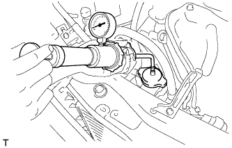
Fill the radiator with coolant and attach a radiator cap tester.
-
Warm up the engine.
-
Using the radiator cap tester, increase the pressure inside the radiator to 118 kPa (1.2 kgf/cm2, 17 psi), and check that the pressure does not drop.
If the pressure drops, check the hoses, radiator and water pump for leaks. If no external leaks are found, check the heater core, cylinder block and cylinder head.
-
-
INSPECT FOR EXHAUST GAS LEAK
-
INSPECT FOR REFRIGERANT LEAK
-
After recharging with refrigerant, inspect for refrigerant leaks using a halogen leak detector.
-
Carry out the test under the following conditions:
-
Turn the ignition switch off.
-
Secure good ventilation (the halogen leak detector may react to volatile gases which are not refrigerant, such as evaporated gasoline and exhaust gas).
-
Repeat the test 2 or 3 times.
-
Make sure that there is some refrigerant remaining in the refrigeration system.
When the compressor is off: approx. 392 to 588 kPa (4.0 to 6.0 kgf/cm2, 57 to 85 psi)
-
-
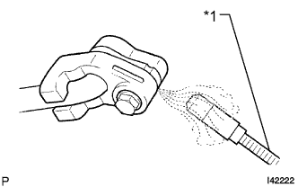
Text in Illustration *1 Halogen Leak Detector Using a halogen leak detector, inspect for refrigerant leaks from the refrigerant lines.
-
Text in Illustration *1 Halogen Leak Detector *2 Drain Hose Bring the halogen leak detector close to the drain hose with the detector's power off, and then turn the detector on.
Tech Tips
-
After the blower motor has stopped, let the cooling unit stand for more than 15 minutes.
-
Bring the halogen leak detector sensor under the drain hose.
-
When bringing the halogen leak detector close to the drain hose, make sure that the halogen leak detector does not react to volatile gases. If it is not possible to avoid interference from volatile gases, the vehicle should be lifted up to allow testing.
-
-
If a refrigerant leak is not detected from the drain hose, remove the blower motor control from the cooling unit. Insert the halogen leak detector sensor into the unit and perform the test.
-
Disconnect the pressure switch connector and leave it for approximately 20 minutes. Bring the halogen leak detector close to the pressure switch and perform the test.
-
-
INSPECT AND ADJUST SHIFT LEVER POSITION (for 2WD)
Tech Tips
-
INSPECT AND ADJUST SHIFT LEVER POSITION (for AWD)
Tech Tips
-
INSPECT AND ADJUST FRONT WHEEL ALIGNMENT
Tech Tips
-
INSPECT IGNITION TIMING
-
Warm up and stop the engine.
-
When using the GTS:
-
Connect the GTS to the DLC3.
-
Start the engine and idle it.
-
Turn the GTS main switch on.
-
Enter the following menus: Powertrain / Engine / Data List / IGN Advance.
Standard ignition timing 5 to 15° BTDC at idle Tech Tips
Refer to the GTS operator's manual for further details.
If the ignition timing is not as specified, check the valve timing.
-
Check that the ignition timing advances immediately when the engine speed is increased.
-
Enter the following menus: Powertrain / Engine / Active Test / Connect the TC and TE1 / ON.
-
Monitor IGN Advance of the Data List.
Standard ignition timing 8 to 12° BTDC at idle Tech Tips
Refer to the GTS operator's manual for further details.
If the ignition timing is not as specified, check the valve timing.
-
Enter the following menus: Connect the TC and TE1 / OFF.
-
Turn the ignition switch off.
-
Disconnect the GTS from the DLC3.
-
-
When not using the GTS:
-
Remove the No. 1 engine cover sub-assembly.
-
Connect the tester probe of a timing light to the wire of the ignition coil connector for the No. 1 cylinder.
Note
Use a timing light that detects primary signals.
-
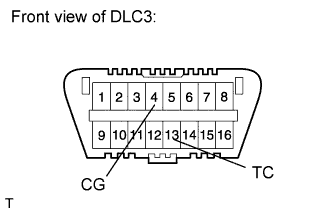
Using SST, connect terminals 13 (TC) and 4 (CG) of the DLC3.
- SST
- 09843-18040
Note
-
Confirm the terminal numbers before connecting them. Connecting the wrong terminals can damage the engine.
-
When checking the ignition timing, the transmission should be in neutral.
-
Using a timing light, check the ignition timing.
Standard ignition timing 8 to 12° BTDC at idle -
Remove SST from the DLC3.
-
Check the ignition timing.
Standard ignition timing 5 to 15° BTDC at idle If the ignition timing is not as specified, check the valve timing.
-
Check that the ignition timing advances immediately when the engine speed is increased.
-
Disconnect the timing light from the engine.
-
Install the No. 1 engine cover sub-assembly.
-
-
-
INSPECT ENGINE IDLE SPEED
-
Warm up and stop the engine.
-
When using the GTS:
-
Connect the GTS to the DLC3.
Note
Switch off all accessories and the A/C before connecting the GTS.
-
Race the engine at 2500 rpm for approximately 90 seconds.
-
Turn the GTS on.
-
Enter the following menus: Powertrain / Engine / Data List / Engine Speed.
Standard idle speed 600 to 700 rpm Tech Tips
Refer to the GTS operator's manual for further details.
Note
When checking the idle speed, the transmission should be in neutral.
If the idle speed is not as specified, check the air intake system.
-
Disconnect the GTS from the DLC3.
-
-
When not using the GTS:
-
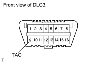
Using SST, connect a tachometer probe to terminal 9 (TAC) of the DLC3.
- SST
- 09843-18030
Note
Confirm the terminal number before connecting the probe. Connecting the wrong terminals can damage the engine.
-
Race the engine at 2500 rpm for approximately 90 seconds.
-
Check the idle speed.
Standard idle speed 600 to 700 rpm Note
-
Turn all electrical systems and the A/C off.
-
Inspect the idle speed with the cooling fans off.
-
When checking the idle speed, the transaxle should be in neutral.
If the speed is not as specified, check the air intake system.
-
-
Disconnect the tachometer probe from the DLC3.
-
-
-
INSPECT CO/HC
Tech Tips
This check determines whether or not the idle CO/HC complies with regulations.
-
Start the engine.
-
Keep the engine speed at 2500 rpm for approximately 180 seconds.
-
Insert the CO/HC meter testing probe at least 40 cm (1.31 ft.) into the tailpipe during idling.
-
Immediately check CO/HC concentration at idle and 2500 rpm.
Tech Tips
-
When performing the 2 mode (2500 rpm and idle) test, follow the measurement order prescribed by the applicable local regulations.
-
If the CO/HC concentration does not comply with regulations, troubleshoot in the order given below.
-
Check for DTCs Click here.
-
See the table below for possible causes, and then inspect and correct the applicable causes if necessary.
CO HC Symptom Causes Normal High Rough idle
-
1. Faulty ignitions
-
Incorrect timing
-
Plugs are contaminated or shorted, or gaps are defective
-
2. Leaky intake and exhaust valves
-
3. Leaky cylinder
Low High Rough idle
(Fluctuating HC reading)
-
1. Vacuum leaks
-
PCV hose
-
Intake manifold
-
Throttle body
-
Brake booster line
-
2. Lean mixture causing misfire
High High Rough idle
(Black smoke from exhaust)
-
1. Restricted air filter
-
2. Faulty SFI system
-
Faulty pressure
-
Defective ECT sensor
-
Faulty ECM
-
Faulty injector
-
Faulty throttle position sensor
-
Faulty MAF sensor
-
-
-
-
INSTALL FRONT FENDER APRON SEAL LH
-
Install the front fender apron seal LH with the 2 bolts and clip.
-
-
INSTALL FRONT FENDER APRON SEAL RH
-
Install the front fender apron seal RH with the 2 bolts and clip.
-
-
INSTALL FRONT FENDER LINER LH
-
INSTALL FRONT FENDER LINER RH
-
INSTALL NO. 2 ENGINE UNDER COVER
-
INSTALL NO. 1 ENGINE UNDER COVER
-
INSTALL NO. 1 ENGINE COVER SUB-ASSEMBLY
-
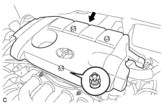
Fit the 3 retainers and install the No. 1 engine cover sub-assembly.
-
-
INSTALL COOL AIR INTAKE DUCT SEAL
-
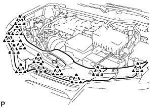
Install the cool air intake duct seal with the 12 clips.
-
-
CHECK SPEED SENSOR SIGNAL
Tech Tips