CYLINDER HEAD GASKET INSTALLATION

-
INSPECT CYLINDER HEAD BOLT
-
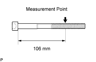
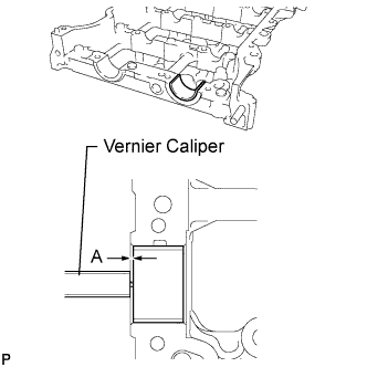
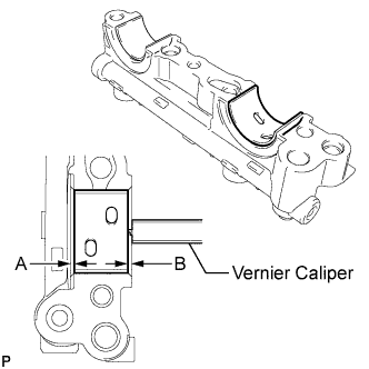
Using a vernier caliper, measure the diameter of the threads at the measurement point.
Standard diameter 10.85 to 11.00 mm (0.427 to 0.433 in.) Minimum diameter 10.6 mm (0.417 in.) Measurement point (distance from the seat) 106 mm (4.17 in.) Tech Tips
-
If the diameter is less than the minimum, replace the cylinder head bolt. Failure to do so may lead to engine damage.
-
If there is any thread deformation, replace the cylinder head bolt with a new one.
-
-
-
INSPECT CYLINDER HEAD SUB-ASSEMBLY
-
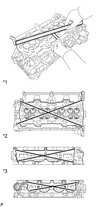
Text in Illustration *1 Cylinder Head Lower Side: *2 Intake Manifold Side: *3 Exhaust Manifold Side: Using a precision straightedge and feeler gauge, measure the warpage of the contact surfaces where the cylinder head contacts the cylinder block and manifold.
Maximum Warpage Item Specified Condition Cylinder head lower side 0.05 mm (0.00197 in.) Intake manifold side 0.10 mm (0.00394 in.) Exhaust manifold side 0.10 mm (0.00394 in.) If the warpage is more than the maximum, replace the cylinder head.
-
Using a dye penetrant, check the intake ports, exhaust ports and cylinder surface for cracks.
If cracked, replace the cylinder head.
-
-
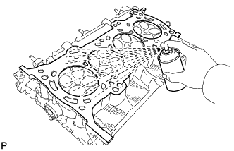
INSTALL CYLINDER HEAD GASKET
-
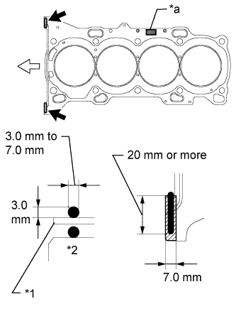
Text in Illustration *1 Cylinder Head Gasket *2 Cylinder Block *a Lot No. 
Seal Packing 
Front Clean the cylinder block and cylinder head sub-assembly with solvent.
-
Apply a continuous line of seal packing to a new cylinder head gasket as shown in the illustration.
Seal Packing Toyota Genuine Seal Packing Black, Three Bond 1207B or equivalent Standard Seal Dimension 3.0 to 7.0 mm (0.118 to 0.276 in.) wide and 3.0 mm (0.118 in.) thick Tech Tips
Apply at least 20 mm (0.787 in.) of seal packing from the inside edge of the protrusion of the cylinder block.
Note
-
Remove any oil from the contact surface.
-
Install the cylinder head gasket within 3 minutes and tighten the bolts within 15 minutes of applying seal packing.
-
-
Place a new cylinder head gasket on the cylinder block surface with the Lot No. stamp facing upward.
Note
Pay attention to the installation direction.
-
-
INSTALL CYLINDER HEAD SUB-ASSEMBLY
Tech Tips
The cylinder head bolts are tightened in 4 progressive steps.
-
Place the cylinder head sub-assembly on the cylinder block.
Note
-
Ensure that no oil is on the mounting surface of the cylinder head sub-assembly.
-
Place the cylinder head sub-assembly on the cylinder block gently in order not to damage the cylinder head gasket with the bottom part of the head.
-
-
Install the plate washers to the cylinder head bolts.
-
Apply a light coat of engine oil to the threads and under the heads of the cylinder head bolts.
-
Step 1:
-
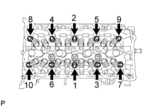
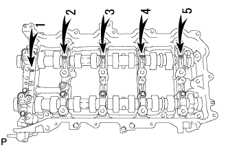
Using a 10 mm bi-hexagon wrench, install and uniformly tighten the 10 cylinder head bolts in several steps, in the sequence shown in the illustration.
- Torque:
- 36 N*m { 367 kgf*cm, 27 ft.*lbf }
Note
Do not drop the plate washer for the cylinder head bolt into the cylinder head sub-assembly.
-
-
Step 2:
-
Tighten the cylinder head bolts again in the sequence shown in the illustration to make sure that they are tightened to the specified torque.
- Torque:
- 36 N*m { 367 kgf*cm, 27 ft.*lbf }
-
-
Step 3:
-
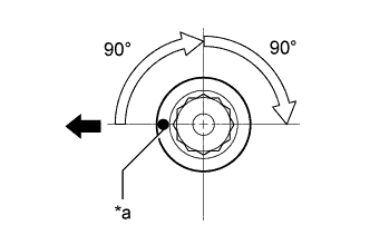
Text in Illustration *a Paint Mark Front Mark each cylinder head bolt head with paint as shown in the illustration.
-
Tighten the cylinder head bolts by 90° in the sequence shown in step 1.
-
-
Step 4:
-
Tighten the cylinder head bolts another 90° in the sequence shown in step 1.
-
Check that the paint marks are now facing rearward.
Note
-
Do not apply oil for at least 4 hours after the installation.
-
Do not start the engine for at least 4 hours after the installation.
-
After the installation, if the seal packing has seeped out, wipe it off.
-
-
-
-
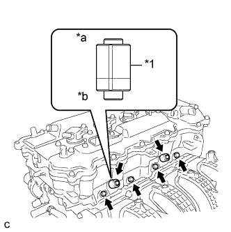
INSTALL VALVE STEM CAP
-
Apply a light coat of engine oil to the valve stem ends.
-
Install the 16 valve stem caps to the cylinder head sub-assembly.
Note
Do not drop the valve stem caps into the cylinder head sub-assembly.
-
-
SET CAMSHAFT TIMING GEAR ASSEMBLY
Tech Tips
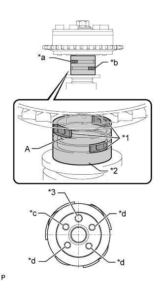
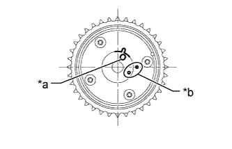
When installing the camshaft timing gear assembly, release the lock pin and set the camshaft timing gear assembly to the advanced position before installation.
-
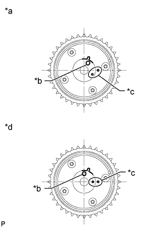
Text in Illustration *a Advanced Position *b Knock Pin Hole *c Alignment Mark *d Retarded Position Check the camshaft timing gear assembly position.
Note
-
If the camshaft timing gear assembly is set to the advanced position, do not let the camshaft timing gear assembly rotate clockwise during installation.
-
If the camshaft timing gear assembly rotates to the retarded position, release the lock pin and set the camshaft timing gear assembly to the advanced position.
-
-

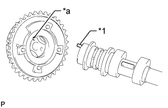
Text in Illustration *1 Knock Pin *a Pin Hole Align and fit the knock pin of the No. 1 camshaft with the pin hole of the camshaft timing gear assembly.
-
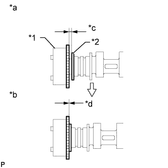
Text in Illustration *1 Camshaft Timing Gear Assembly *2 Camshaft Flange *a Incorrect *b Correct *c Clearance *d No Clearance Check that there is no clearance between the camshaft timing gear assembly and camshaft flange.
-
Secure the camshaft in place by hand, and then install the installation bolt of the camshaft timing gear assembly by hand.
Note
Do not use any tools to install the bolt. If the bolt is installed using a tool, the lock pin will be damaged.
-
Release the lock pin.
Text in Illustration *1 Rubber *2 Vinyl Tape *3 Knock Pin *a Retard Side Path *b Advance Side Path *c Open *d Close
-
Clean the camshaft journal with non-residue solvent.
-
Cover the 4 oil paths of the cam journal with vinyl tape as shown in the illustration.
Tech Tips
There are 4 oil paths in the grooves of the camshaft. Plug three of the paths with pieces of rubber.
-
Open a hole at port (A) shown in the illustration.
-
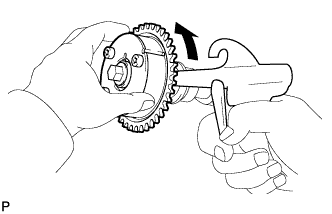
While applying approximately 200 kPa (2.0 kgf/ cm2, 29 psi) of air pressure to the oil path, forcibly turn the camshaft timing gear assembly in the advance direction (counterclockwise).
CAUTION:
Cover the path with a piece of cloth when applying pressure to keep oil from spraying.
Note
Do not allow the camshaft timing gear assembly to lock. If it locks, release the lock pin again.
Tech Tips
-
The camshaft timing gear assembly may be turned in the advance direction without applying any force.
-
If enough air pressure cannot be applied because of air leakage from the port, releasing the lock pin may be difficult.
-
-
Remove the vinyl tape and rubber pieces from the camshaft.
-
-
Remove the bolt and camshaft timing gear assembly.
Note
Do not allow the camshaft timing gear assembly to lock. If it locks, release the lock pin again.
-
-
INSTALL VALVE LASH ADJUSTER ASSEMBLY
-
Inspect the valve lash adjuster assemblies before installing them Click here.
-
Install the 16 valve lash adjuster assemblies to the cylinder head sub-assembly.
Note
Install each valve lash adjuster assembly to the same place it was removed from.
-
-
INSTALL NO. 1 VALVE ROCKER ARM SUB-ASSEMBLY
-
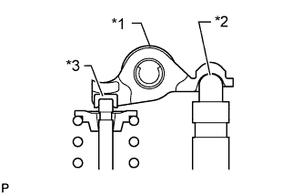
Text in Illustration *1 No. 1 Valve Rocker Arm Sub-assembly *2 Valve Lash Adjuster Assembly *3 Valve Stem Cap Apply engine oil to the valve lash adjuster assembly tips and valve stem caps.
-
Install the 16 No. 1 valve rocker arm sub-assemblies as shown in the illustration.
-
-
INSTALL NO. 2 CAMSHAFT BEARING
-
Clean the No. 2 camshaft bearing.
-
Install the camshaft bearing to the camshaft housing.
-
Using a vernier caliper, measure the distance between the camshaft housing edge and the camshaft bearing edge.
Standard distance 1.15 to 1.85 mm (0.0453 to 0.0728 in.)
-
-
INSTALL NO. 1 CAMSHAFT BEARING
-
Clean the No. 1 camshaft bearing.
-
Install the camshaft bearing to the No. 1 camshaft bearing cap.
-
Using a vernier caliper, measure the distance between the camshaft bearing cap edge and the camshaft bearing edge.
Standard dimension A - B or B - A 0 to 0.7 mm (0 to 0.0276 in.)
-
-
INSTALL OIL CONTROL VALVE FILTER
-
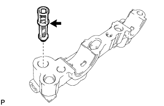
Install the oil control valve filter to the No. 1 camshaft bearing cap.
-
-
INSTALL CAMSHAFT
-
Clean the camshaft journals, camshaft housing sub-assembly and camshaft bearing caps.
-
Apply a light coat of engine oil to the camshaft journal, camshaft housing sub-assembly and camshaft bearing caps.
-
Install the No. 1 camshaft and No. 2 camshaft to the camshaft housing sub-assembly.
-
-
INSTALL CAMSHAFT BEARING CAP
-
Confirm the marks and numbers on the camshaft bearing caps and place them in their proper positions and directions.
-
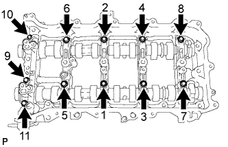
Install the 11 bolts in the order shown in the illustration.
- Torque:
- 16 N*m { 163 kgf*cm, 12 ft.*lbf }
Note
Make sure that the camshafts rotates smoothly after installing the camshaft bearing caps.
-
-
INSTALL CAMSHAFT HOUSING SUB-ASSEMBLY
-
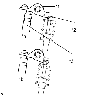
Text in Illustration *1 No. 1 Valve Rocker Arm Sub-assembly *2 Valve Stem Cap *3 Valve Lash Adjuster Assembly *a Incorrect *b Correct Check that the valve rocker arms are installed as shown in the illustration.
-
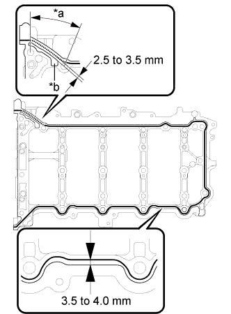
Text in Illustration *a Dashed Line *b Groove Apply seal packing in a continuous line as shown in the illustration.
Seal Packing Toyota Genuine Seal Packing Black, Three Bond 1207B or equivalent Apply Seal Packing as Follows Area Seal Packing Diameter Application Position Continuous Line 3.0 to 4.0 mm (0.118 to 0.157 in.) Distance from edge of camshaft housing sub-assembly to center of seal packing: 3.5 to 4.0 mm (0.138 to 0.157 in.) Dashed Line Distance from outside edge of groove to center of seal packing: 2.5 to 3.5 mm (0.0984 to 0.138 in.) Note
-
Remove any oil from the contact surface.
-
Install the camshaft housing sub-assembly within 3 minutes and tighten the bolts within 10 minutes of applying seal packing.
-
-
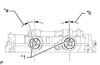
Text in Illustration *1 Knock Pin *a Approximately 17° *b Approximately 2° Position the knock pin of the No. 1 camshaft and No. 2 camshaft as shown in the illustration.
-
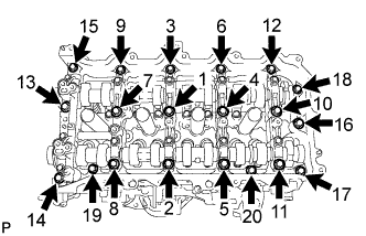
Install the camshaft housing sub-assembly, and then install the 20 bolts in the order shown in the illustration.
- Torque:
- 27 N*m { 275 kgf*cm, 20 ft.*lbf }
Note
-
Do not apply oil for at least 4 hours after the installation.
-
Do not start the engine for at least 4 hours after the installation.
-
Thoroughly wipe clean any seal packing.
-
-
INSTALL CAMSHAFT TIMING GEAR ASSEMBLY
-
Text in Illustration *a Knock Pin Hole *b Alignment Mark Check the camshaft timing gear assembly position.
If the camshaft timing gear assembly is not set to the advanced position, release the lock pin and reset the camshaft timing gear assembly (Refer to the "Set Camshaft Timing Gear Assembly" procedure).
-
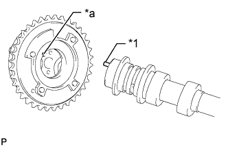
Text in Illustration *1 Knock Pin *a Pin Hole Align and fit the knock pin of the No. 1 camshaft with the pin hole of the camshaft timing gear assembly.
-
Text in Illustration *1 Camshaft Timing Gear Assembly *2 Camshaft Flange *a Incorrect *b Correct *c Clearance *d No Clearance Check that there is no clearance between the camshaft timing gear assembly and camshaft flange.
-
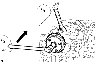
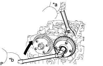
Text in Illustration *a Hold *b Turn Using a wrench to hold the hexagonal portion of the No. 1 camshaft, install the bolt.
- Torque:
- 85 N*m { 867 kgf*cm, 63 ft.*lbf }
Note
-
Be careful not to damage the cylinder head sub-assembly or spark plug tube with the wrench.
-
Do not disassemble the camshaft timing gear assembly.
-
-
INSTALL CAMSHAFT TIMING EXHAUST GEAR ASSEMBLY
-
Text in Illustration *1 Knock Pin *a Pin Hole Align and fit the knock pin of the No. 2 camshaft with the pin hole of the camshaft timing exhaust gear assembly.
-
Text in Illustration *1 Camshaft Timing Exhaust Gear Assembly *2 Camshaft Flange *a Incorrect *b Correct *c Clearance *d No Clearance Check that there is no clearance between the camshaft timing exhaust gear assembly and camshaft flange.
-
*a Hold *b Turn Using a wrench to hold the hexagonal portion of the No. 2 camshaft, install the bolt.
- Torque:
- 85 N*m { 867 kgf*cm, 63 ft.*lbf }
Note
-
Be careful not to damage the cylinder head sub-assembly or spark plug tube with the wrench.
-
Do not disassemble the camshaft timing exhaust gear assembly.
-
-
ADD ENGINE OIL
-
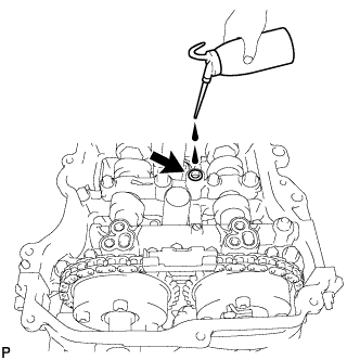
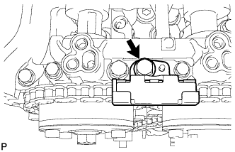
Add 50 cc (3.1 cu.in) of engine oil into the oil hole shown in the illustration.
Note
-
Oil must be added if the valve lash adjuster assemblies were removed.
-
Make sure that the low pressure chamber and oil paths of the valve lash adjuster assemblies are full of engine oil.
-
-
-
SET NO. 1 CYLINDER TO TDC/COMPRESSION
-
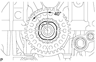
Temporarily install the crankshaft pulley bolt.
-
Rotate the crankshaft 40° counterclockwise to position the crankshaft pulley set key as shown in the illustration.
-
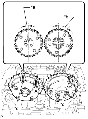
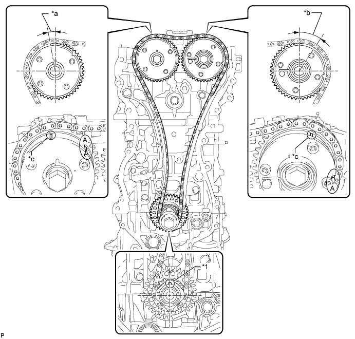
Text in Illustration *a Approximately 7° *b Approximately 32° *c Timing Mark Check that the timing marks of the camshaft timing gear assembly and camshaft timing exhaust gear assembly are as shown in the illustration.
Tech Tips
"A" is not a timing mark.
-
-
INSTALL NO. 1 CHAIN VIBRATION DAMPER
-
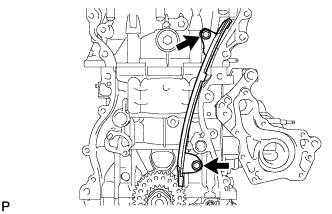
Install the No. 1 chain vibration damper with the 2 bolts in the order shown in the illustration.
- Torque:
- 21 N*m { 214 kgf*cm, 15 ft.*lbf }
-
-
INSTALL CHAIN SUB-ASSEMBLY
-
Place the chain sub-assembly onto the camshaft timing gear assembly, camshaft timing exhaust gear assembly and crankshaft timing sprocket.
Tech Tips
-
Make sure the mark plate of the chain sub-assembly faces away from the engine.
-
It is not necessary to install the chain sub-assembly to the teeth of the camshaft timing gear assembly, camshaft timing exhaust gear assembly and crankshaft timing sprocket.
-
-
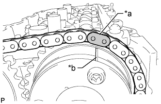
Text in Illustration *a Mark Plate *b Timing Mark Align the mark plate (yellow or gold) of the chain sub-assembly with the timing mark of the camshaft timing exhaust gear assembly and install the chain sub-assembly to the camshaft timing exhaust gear assembly.
-
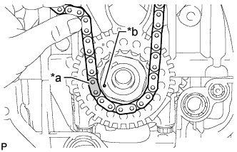
Text in Illustration *a Mark Plate *b Timing Mark Align the mark plate (pink or gold) of the chain sub-assembly with the timing mark of the crankshaft timing sprocket and install the chain sub-assembly to the crankshaft timing sprocket.
-
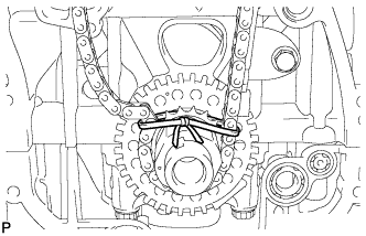
Tie a string above the crankshaft timing sprocket to secure the chain sub-assembly.
-
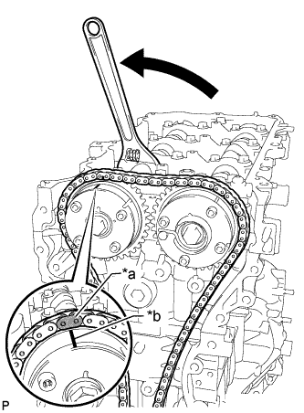
Text in Illustration *a Mark Plate *b Timing Mark Using a wrench, hold the hexagonal portion of the No. 1 camshaft, rotate the No. 1 camshaft counterclockwise with a wrench, align the timing mark of the camshaft timing gear assembly with the mark plate (yellow or gold) of the chain sub-assembly and install the chain sub-assembly to the camshaft timing gear assembly.
Tech Tips
Hold the No. 1 camshaft in place with a wrench until the No. 1 chain tensioner assembly is installed.
-
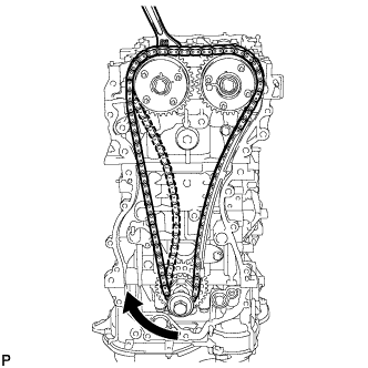
Remove the string above the crankshaft timing sprocket, rotate the crankshaft clockwise, and loosen the chain sub-assembly so that the chain tensioner slipper can be installed.
Note
Make sure the chain sub-assembly is secure.
-
-
INSTALL CHAIN TENSIONER SLIPPER
-
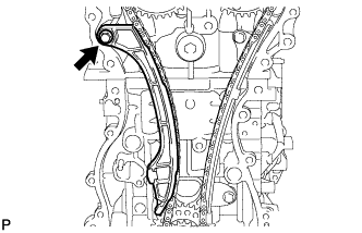
Install the chain tensioner slipper with the bolt.
- Torque:
- 21 N*m { 214 kgf*cm, 15 ft.*lbf }
-
-
INSTALL NO. 1 CHAIN TENSIONER ASSEMBLY
-
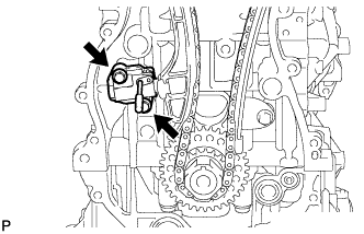
Install a new gasket and the No. 1 chain tensioner assembly with the 2 bolts.
- Torque:
- 10 N*m { 102 kgf*cm, 7 ft.*lbf }
-
Remove the pin from the stopper plate.
-
-
INSTALL TIMING CHAIN GUIDE
-
Install the timing chain guide with the bolt
- Torque:
- 21 N*m { 214 kgf*cm, 15 ft.*lbf }
-
-
CHECK NO. 1 CYLINDER TO TDC/COMPRESSION
-
Temporarily install the crankshaft pulley bolt.
Text in Illustration *1 Crankshaft Pulley Set Key - - *a Approximately 7° *b Approximately 32° *c Timing Mark - - -
Rotate the crankshaft clockwise and align the crankshaft pulley set key as shown in the illustration.
Tech Tips
"A" is not a timing mark.
-
Check that the timing marks on the camshaft timing gear assembly and camshaft timing exhaust gear assembly are as shown in the illustration.
-
Remove the crankshaft pulley bolt.
-
-
INSTALL TIMING CHAIN COVER SUB-ASSEMBLY
-
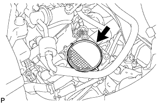
INSTALL INTAKE MANIFOLD
-
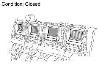
Close the tumble control valves.
Note
The tumble control valves may be damaged if they are not closed before installing the intake manifold.
Tech Tips
Connect the battery to the terminals of the actuator to operate the motor and close the valves Click here.
-
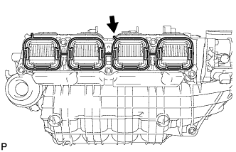
Install a new gasket to the intake manifold.
-
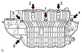
Install the intake manifold by tightening the 6 bolts in the sequence shown in the illustration.
- Torque:
- 21 N*m { 214 kgf*cm, 15 ft.*lbf }
-
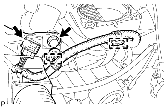
Connect the intake air control actuator connector.
-
Attach the 2 clamps to the intake manifold and bracket.
-
Install the wire harness with the bolt.
- Torque:
- 8.4 N*m { 86 kgf*cm, 74 in.*lbf }
-
Install the wire harness bracket with the bolt.
- Torque:
- 8.4 N*m { 86 kgf*cm, 74 in.*lbf }
-
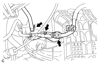
Connect the fuel vapor feed hose, clamp and connector.
-
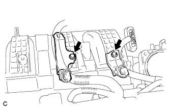
Install the 2 wire harness brackets with the 2 bolts.
- Torque:
- 8.4 N*m { 86 kgf*cm, 74 in.*lbf }
-
-
CONNECT NO. 2 VENTILATION HOSE
-
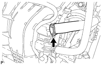
Connect the No. 2 ventilation hose to the intake manifold.
-
-
INSTALL FUEL DELIVERY PIPE SUB-ASSEMBLY
-
Text in Illustration *1 Fuel Delivery Spacer *a Fuel Delivery Pipe Side *b Cylinder Head Side Install 4 new injector vibration insulators to the cylinder head.
-
Install the 2 fuel delivery spacers onto the cylinder head.
Tech Tips
Install the fuel delivery spacer so that the longer protrusion is on the cylinder head side.
-
Install the fuel delivery pipe sub-assembly together with the 4 fuel injectors to the cylinder head, and then temporarily install the 2 bolts.
Note
Be careful not to drop the fuel injectors when installing the fuel delivery pipe sub-assembly.
-
Tighten the 2 bolts to the specified torque.
- Torque:
- 21 N*m { 214 kgf*cm, 15 ft.*lbf }
Note
-
Do not drop the fuel injectors when installing the fuel delivery pipe sub-assembly.
-
Check that the fuel injector assemblies rotate smoothly after installing the fuel delivery pipe sub-assembly.
-
-
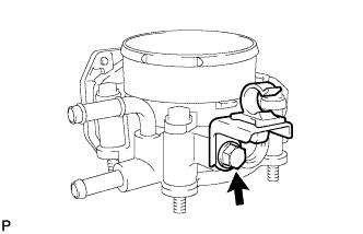
INSTALL THROTTLE BODY ASSEMBLY
-
Install a new gasket to the intake manifold.
-
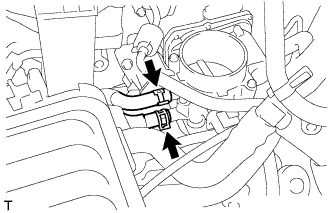
Install the fuel tube bracket with the bolt.
- Torque:
- 7.5 N*m { 76 kgf*cm, 66 in.*lbf }
-
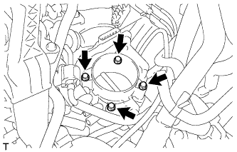
Install the throttle body assembly with the 4 bolts.
- Torque:
- 10 N*m { 102 kgf*cm, 7 ft.*lbf }
-
Connect the 2 water by-pass hoses to the throttle body.
-
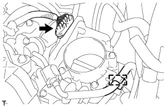
Connect the throttle body assembly connector.
-
Connect the fuel tube to the clamp.
-
-
INSTALL EXHAUST MANIFOLD CONVERTER SUB-ASSEMBLY
-
Install the exhaust manifold converter sub-assembly Click here.
-
-
INSTALL ENGINE ASSEMBLY WITH TRANSAXLE
-
Install the engine assembly with transaxle Click here.
-