CAMSHAFT INSTALLATION

-
INSTALL NO. 2 CAMSHAFT BEARING
-
Clean the No. 2 camshaft bearing.
-
Install the camshaft bearing to the camshaft housing.
-
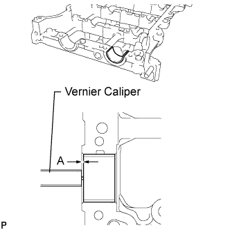
Using a vernier caliper, measure the distance between the camshaft housing edge and the camshaft bearing edge.
Standard distance 1.15 to 1.85 mm (0.0453 to 0.0728 in.)
-
-
INSTALL NO. 1 CAMSHAFT BEARING
-
Clean the No. 1 camshaft bearing.
-
Install the camshaft bearing to the No. 1 camshaft bearing cap.
-
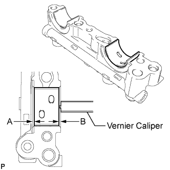
Using a vernier caliper, measure the distance between the camshaft bearing cap edge and the camshaft bearing edge.
Standard dimension A - B or B - A 0 to 0.7 mm (0 to 0.0276 in.)
-
-
INSTALL OIL CONTROL VALVE FILTER
-
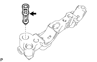
Install the oil control valve filter to the No. 1 camshaft bearing cap.
-
-
INSTALL CAMSHAFT TIMING EXHAUST GEAR ASSEMBLY
-
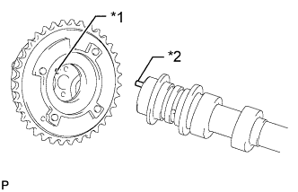
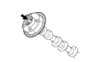
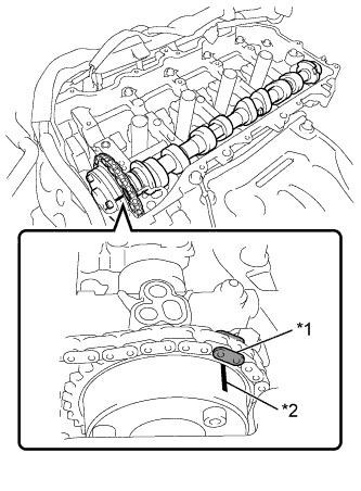
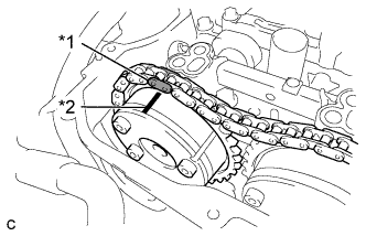
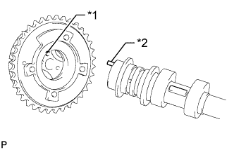
Text in Illustration *1 Knock Pin Hole *2 Knock Pin Align and attach the knock pin of the No. 2 camshaft with the pin hole of the camshaft timing exhaust gear assembly.
-
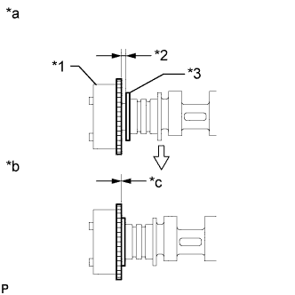
Text in Illustration *1 Camshaft Timing Exhaust Gear *2 Clearance *3 Camshaft Flange *a INCORRECT *b CORRECT *c No Clearance Check that there is no clearance between the camshaft timing exhaust gear assembly and camshaft flange.
-
Fix the camshaft timing exhaust gear assembly with the bolt.
- Torque:
- 85 N*m { 867 kgf*cm, 63 ft.*lbf }
Note
Do not disassemble the camshaft timing exhaust gear.
-
-
SET NO. 1 CYLINDER TO TDC/COMPRESSION
-
Text in Illustration *1 Timing Notch Turn the crankshaft pulley until its timing notch (groove) and the timing mark "0" of the timing chain cover are aligned.
-
-
INSTALL NO. 2 CAMSHAFT
-
Text in Illustration *1 Valve Rocker Arm *2 Valve Lash Adjuster *3 Valve Stem Cap Make sure that the valve rocker arms are installed as shown in the illustration.
-
Clean the camshaft journals.
-
Apply a light coat of engine oil to the camshaft journals, camshaft housings and bearing caps.
-
Text in Illustration *1 Paint Mark *2 Matchmark Hold up the chain and align the matchmark and the paint mark and install the camshaft.
-
-
INSTALL CAMSHAFT
-
Text in Illustration *1 Valve Rocker Arm *2 Valve Lash Adjuster *3 Valve Stem Cap Make sure that the valve rocker arms are installed as shown in the illustration.
-
Clean the camshaft journals.
-
Apply a light coat of engine oil to the camshaft journals, camshaft housings and bearing caps.
-
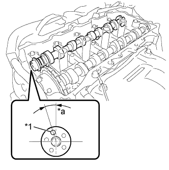
Text in Illustration *1 Knock Pin *a Approximately 17° Install the camshaft to the camshaft housing as shown in the illustration.
-
-
INSTALL CAMSHAFT BEARING CAP
-
Confirm the marks and numbers on the camshaft bearing caps and place them in their proper positions and directions.
-
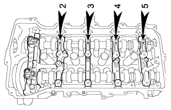
Using several steps, uniformly tighten the 10 bolts in the sequence shown in the illustration.
- Torque:
- 27 N*m { 275 kgf*cm, 20 ft.*lbf }
-
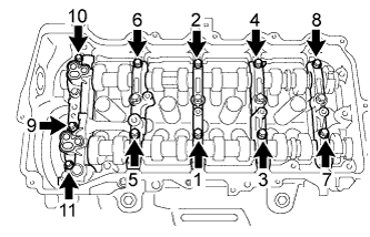
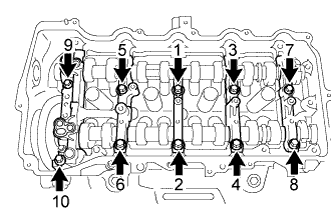
Using several steps, uniformly tighten the 11 bolts in the sequence shown in the illustration.
- Torque:
- 16 N*m { 163 kgf*cm, 12 ft.*lbf }
-
Check the torque of each bolt again.
-
-
INSTALL CAMSHAFT TIMING GEAR ASSEMBLY
-
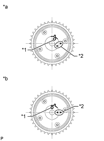
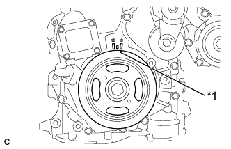
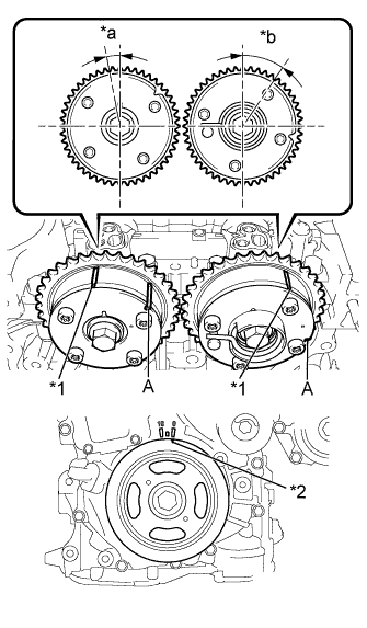
Text in Illustration *1 Knock Pin Hole *2 Alignment Mark *a Advanced Position *b Retarded Position Check the camshaft timing gear position.
Note
-
If the camshaft timing gear is set to the advanced position, do not let the camshaft timing gear rotate clockwise during installation.
-
If the camshaft timing gear has rotated to the most retarded position, make sure to release the lock pin and set the camshaft timing gear to the most advanced position before tightening the camshaft timing gear.
-
-
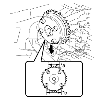
Text in Illustration *a Narrow *b Wide Install the camshaft timing gear as shown in the illustration.
-
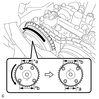
Text in Illustration *a Narrow *b Wide Turn the camshaft timing gear approximately 180° counterclockwise.
-
Text in Illustration *1 Paint Mark *2 Matchmark Align the paint mark with the matchmark to install the chain.
-
Text in Illustration *1 Knock Pin Hole *2 Knock Pin Align and attach the knock pin of the No. 1 camshaft with the pin hole of the camshaft timing gear.
-
Text in Illustration *1 Camshaft Timing Gear *2 Clearance *3 Camshaft Flange *a INCORRECT *b CORRECT *c No Clearance Check that there is no clearance between the camshaft timing gear and camshaft flange.
-
Secure the camshaft in place by hand, and then install the installation bolt of the camshaft timing gear by hand.
Note
Do not use any tools to install the bolt. If the bolt is installed using a tool, the lock pin will be damaged.
-
If the lock pin has not been released, release it.
-
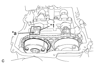
Text in Illustration *1 Adhesive Tape Sealing Area *a Make a Hole After cleaning and degreasing the intake side VVT oil hole on the No. 1 camshaft bearing cap, completely seal the oil hole with adhesive tape or equivalent as shown in the illustration to prevent air from leaking.
Note
Be sure to seal the oil hole completely because air leaks due to insufficient sealing will prevent the lock pin from being released.
-
Make a hole in the adhesive tape covering the oil hole as shown in the illustration. (Procedure A)
-
Apply approximately 200 kPa (2.0 kgf/ cm2, 29 psi) of air pressure to the hole made in procedure A to release the lock pin.
Note
-
If air leaks out, reattach the adhesive tape.
-
Cover the oil hole with a piece of cloth when applying air pressure to prevent oil from spraying.
-
-
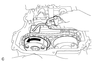
Forcibly turn the camshaft timing gear in the advance direction (counterclockwise).
Tech Tips
Depending on the air pressure applied, the camshaft timing gear may turn in the advance direction without assistance by hand.
-
Remove the adhesive tape from the No. 1 camshaft bearing cap.
-
-
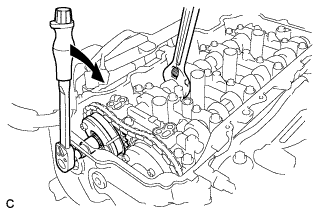
Using a wrench to hold the hexagonal portion of the No. 1 camshaft, install the bolt.
- Torque:
- 85 N*m { 867 kgf*cm, 63 ft.*lbf }
Note
Be careful not to damage the cylinder head or spark plug tube with the wrench.
-
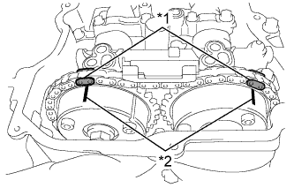
Text in Illustration *1 Paint Mark *2 Matchmark Check that each matchmark of the camshaft timing gear and camshaft timing exhaust gear are aligned with each matchmark located as shown in the illustration.
-
-
ADD ENGINE OIL
-
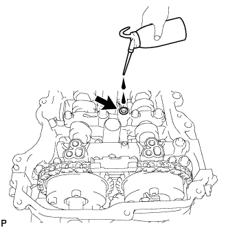
Add 50 cc (3.1 cu. in) of engine oil into the oil hole shown in the illustration.
Note
-
Oil must be added if the lash adjusters were removed.
-
Make sure that the low pressure chamber and oil paths of the lash adjusters are full of engine oil.
-
-
-
INSTALL TIMING CHAIN GUIDE
-
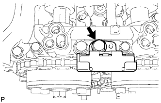
Install the timing chain guide with the bolt
- Torque:
- 21 N*m { 214 kgf*cm, 15 ft.*lbf }
-
-
INSTALL NO. 1 CHAIN TENSIONER ASSEMBLY
-
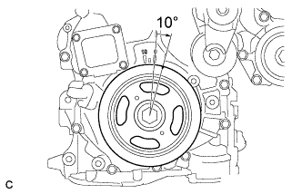
Turn the crankshaft approximately 10° clockwise.
-
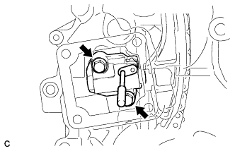
Install a new gasket and the chain tensioner with the 2 bolts.
- Torque:
- 10 N*m { 102 kgf*cm, 7 ft.*lbf }
Note
Make sure not to drop the gasket inside the timing chain cover.
-
Remove the pin from the stopper plate.
-
-
CHECK NO. 1 CYLINDER TO TDC/COMPRESSION
-
Text in Illustration *1 Timing Mark *2 Timing Notch *a Approximately 7° *b Approximately 32° Turn the crankshaft pulley until its timing notch (groove) and the timing mark "0" of the timing chain cover are aligned.
-
Check that the timing marks of the camshaft timing gears are as shown in the illustration. If not, turn the crankshaft 1 revolution (360°) to align the timing marks as shown in the illustration.
Tech Tips
"A" is not a timing mark.
-
-
INSTALL TIMING CHAIN COVER PLATE
-
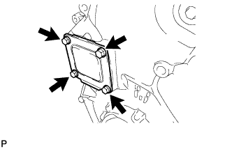
Install a new gasket and the timing chain cover plate with the 4 bolts.
- Torque:
- 10 N*m { 102 kgf*cm, 7 ft.*lbf }
-
-
INSTALL TIMING CHAIN COVER TIGHT PLUG
-
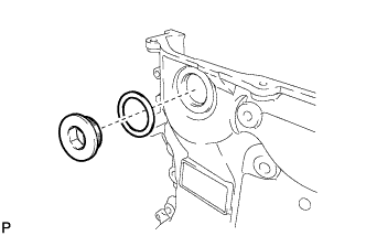
Using a 14 mm hexagon wrench, install a new gasket and the plug.
- Torque:
- 30 N*m { 306 kgf*cm, 22 ft.*lbf }
-
-
INSTALL CYLINDER HEAD COVER SUB-ASSEMBLY
-
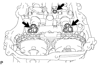
Apply a light coat of engine oil to 3 new gaskets.
-
Install the 3 gaskets to the camshaft bearing caps.
-
Install a new gasket to the cylinder head cover.
Note
Remove any oil from the contact surfaces.
-
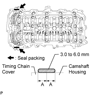
Apply seal packing as shown in the illustration.
Seal packing Toyota Genuine Seal Packing Black, Three Bond 1207B or equivalent Standard seal diameter 3.0 to 6.0 mm (0.118 to 0.236 in.) Application width A 5.0 mm (0.197 in.) Note
-
Remove any oil from the contact surfaces.
-
Install the cylinder head cover within 3 minutes and tighten the bolts within 15 minutes of applying seal packing.
-
-
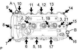
Align the cylinder head cover with pin A. Then align the cylinder head cover with pin B and install the cylinder head cover.
-
Install 3 new seal washers and the 16 bolts, and then tighten the bolts in the order shown in the illustration.
- Torque:
- 12 N*m { 122 kgf*cm, 9 ft.*lbf }
Note
Do not apply oil for at least 4 hours after the installation.
-
-
INSTALL IGNITION COIL ASSEMBLY
-
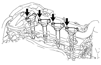
Install the 4 ignition coil assemblies with the 4 bolts.
- Torque:
- 10 N*m { 102 kgf*cm, 7 ft.*lbf }
-
Connect the 4 ignition coil assembly connectors.
-
-
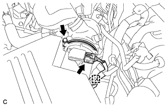
CONNECT ENGINE WIRE
-
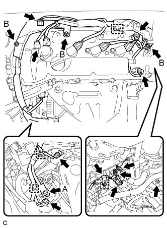
Connect the connectors and clamps, and install the engine wire to the engine with the bolts and nuts.
- Torque:
- Nut A
- 9.8 N*m { 100 kgf*cm, 87 in.*lbf }
- Nut B
- 8.4 N*m { 86 kgf*cm, 74 in.*lbf }
- Bolt
- 8.4 N*m { 86 kgf*cm, 74 in.*lbf }
-
-
CONNECT VENTILATION HOSE ASSEMBLY
-
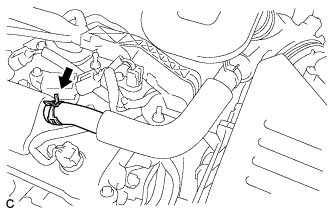
Connect the ventilation hose to the cylinder head cover.
-
-
INSTALL ENGINE MOVING CONTROL ROD
-
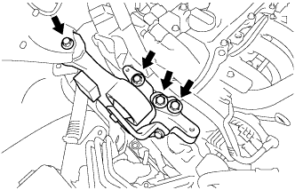
Temporarily install the engine moving control rod with the 4 bolts.
-
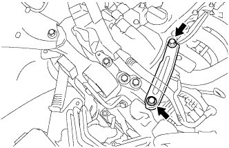
Temporarily install the No. 2 engine mounting stay with the 2 bolts
-
Tighten the 6 bolts.
- Torque:
- 38 N*m { 387 kgf*cm, 28 ft.*lbf }
-
-
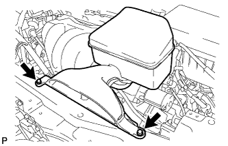
INSTALL AIR CLEANER CASE SUB-ASSEMBLY
-
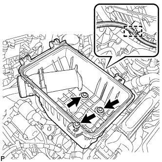
Install the air cleaner case sub-assembly with the 3 bolts.
- Torque:
- 5.0 N*m { 51 kgf*cm, 44 in.*lbf }
-
connect the wire harness clamp.
-
-
INSTALL AIR CLEANER FILTER ELEMENT SUB-ASSEMBLY
-
Install the air cleaner filter element sub-assembly.
-
-
INSTALL AIR CLEANER CAP SUB-ASSEMBLY
-
Install the air cleaner cap sub-assembly with the 2 bolts.
- Torque:
- 5.0 N*m { 51 kgf*cm, 44 in.*lbf }
-
Connect the air cleaner hose and tighten the hose clamp bolt.
-
Connect the mass air flow meter connector and install the wire harness clamp to the air cleaner cap.
-
-
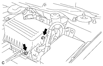
INSTALL INLET AIR CLEANER ASSEMBLY
-
Install the inlet air cleaner assembly with the 2 bolts.
- Torque:
- 5.0 N*m { 51 kgf*cm, 44 in.*lbf }
-
-
CONNECT CABLE TO NEGATIVE BATTERY TERMINAL
Note
When disconnecting the cable, some systems need to be initialized after the cable is reconnected Click here.
-
INSPECT FOR OIL LEAK
-
INSTALL FRONT FENDER APRON SEAL RH
-
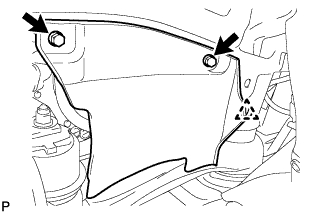
Install the front fender apron seal RH with the 2 bolts and clip.
-
-
INSTALL FRONT FENDER LINER RH
-
INSTALL NO. 1 ENGINE UNDER COVER
-
INSTALL NO. 1 ENGINE COVER SUB-ASSEMBLY
-
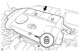
Fit the 3 retainers and install the No. 1 engine cover sub-assembly.
-
-
INSTALL FRONT WHEEL RH