SFI SYSTEM FREEZE FRAME DATA

-
DESCRIPTION
-
The ECM records vehicle and driving condition information as freeze frame data the moment a DTC is stored. When troubleshooting, freeze frame data can be helpful in determining whether the vehicle was moving or stationary, whether the engine was warmed up or not, whether the air fuel ratio was lean or rich, as well as other data recorded at the time of a malfunction.
Tech Tips
If it is impossible to replicate the problem even though a DTC is output, confirm the freeze frame data.
-
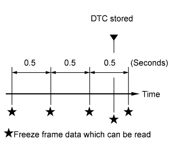
The ECM records engine conditions in the form of freeze frame data every 0.5 seconds. Using the GTS, 5 separate sets of freeze frame data, including the data values at the time when the DTC is stored, can be checked.
-
3 data sets before the DTC is stored.
-
1 data set when the DTC is stored.
-
1 data set after the DTC is stored.
-
These data sets can be used to simulate the condition of the vehicle around the time of the occurrence of the malfunction. The data may assist in identifying the cause of the malfunction, and judging whether it was temporary or not.
-
-
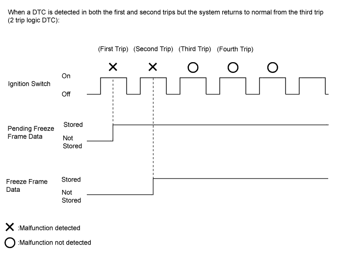
PENDING FREEZE FRAME DATA
Tech Tips
Pending freeze frame data is stored when a 2 trip DTC is first detected during the first trip.
-
Connect the GTS to the DLC3.
-
Turn the ignition switch to ON.
-
Turn the GTS on.
-
Enter the following menus: Powertrain / Engine / Trouble Codes.
-
Select a DTC in order to display its pending freeze frame data.
Tech Tips
-
Pending freeze frame data is cleared when any of the following occurs.
-
Using the GTS, the DTCs cleared.
-
The cable is disconnected from the negative (-) battery terminal.
-
40 trips with the engine fully warmed up have been performed after returning to normal. (Pending freeze frame data will not be cleared by only returning the system to normal.)
-
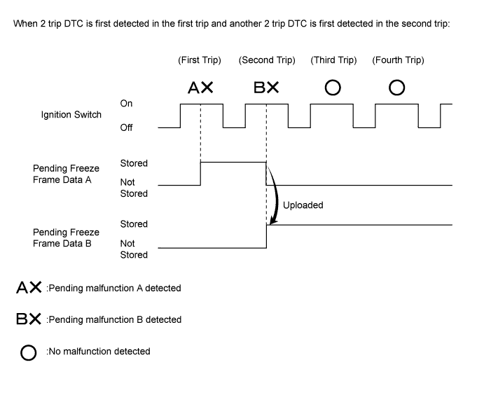
With previous pending freeze frame data stored, if pending freeze frame data is newly stored when a 2 trip DTC is detected in the first trip, the old freeze frame data will be replaced with the new one of the newly detected DTC in the next trip.
-
-
-
LIST OF FREEZE FRAME DATA
GTS Display Measurement Item Diagnostic Note Vehicle Speed Vehicle speed The speed indicated on the speedometer. Engine Speed Engine speed - Calculate Load Calculated load The load calculated by the ECM. Vehicle Load Vehicle load The load percentage in terms of the maximum intake air flow amount. MAF Air flow rate from mass air flow meter sub-assembly If the value is approximately 0.0 gm/sec:
-
The mass air flow meter sub-assembly power source circuit is open.
-
The VG circuit is open or shorted.
If 271.0 gm/sec or more:
-
The E2G circuit is open.
Atmosphere Pressure Atmospheric pressure - Coolant Temp Engine coolant temperature
-
If the value is -40°C (-40°F), the sensor circuit is open.
-
If the value is 140°C (284°F), the sensor circuit is shorted.
Intake Air Intake air temperature
-
If the value is -40°C (-40°F), the sensor circuit is open.
-
If the value is 140°C (284°F), the sensor circuit is shorted.
Engine Run Time Accumulated engine running time - Initial Engine Coolant Temp Engine coolant temperature at engine start - Initial Intake Air Temp Initial intake air temperature - Battery Voltage Battery voltage - Glow Indicator Supported Glow indicator supported - Glow Indicator Glow indicator - Accel Sens. No. 1 Volt % Absolute accelerator pedal position No. 1 - Accel Sens. No. 2 Volt % Absolute accelerator pedal position No. 2 - Throttle Sensor Volt % Absolute throttle position sensor The throttle opening angle recognized by the ECM. Throttl Sensor #2 Volt % Absolute throttle position sensor #2 The throttle opening angle recognized by the ECM. Throttle Sensor Position Throttle sensor positioning The calculated value based on VTA1. Throttle Motor DUTY Throttle actuator - Throttle Position Throttle valve opening angle When the engine stalls, is difficult to start, or idles roughly ISC Flow Flow rate calculated using information from mass air flow meter sub-assembly When the engine stalls, is difficult to start, or idles roughly ISC Position Requested throttle opening amount calculated using ISC control This is the throttle valve opening amount while the engine is idling (the throttle valve opening amount necessary to maintain ISC air flow). ISC Feedback Value ISC feedback amount When the engine stalls, is difficult to start, or idles roughly ISC Learning Value ISC learned airflow value When the engine stalls, is difficult to start, or idles roughly Electric Load Feedback Val Compensation flow rate according to electrical load When the engine stalls, is difficult to start, or idles roughly Air Conditioner FB Val Compensation flow rate according to air conditioner load When the engine stalls, is difficult to start, or idles roughly Low Revolution Control Low engine speed control operation state When the engine stalls, is difficult to start, or idles roughly N Range Status Shift lever N status When the engine stalls, is difficult to start, or idles roughly Eng Stall Control FB Flow Intake air compensation flow rate When the engine stalls, is difficult to start, or idles roughly Deposit Loss Flow Flow loss due to deposits
-
This value indicates the amount of compensation for a decrease in flow passage area due to the buildup of deposits on the throttle valve.
-
Check this value for reference when the engine stalls, is difficult to start, or idles roughly.
-
When the ISC learned value is initialized by disconnecting the battery negative terminal or removing the fuses (EFI NO. 1 and ETCS fuses), performing the following procedures in order to quickly relearn the Deposit Loss Flow value. After the Deposit Loss Flow has been relearned, gradual fine adjustments will continue automatically.
-
Start the engine cold and allow the engine to idle.
-
After the engine is warmed up (engine coolant temperature is above 80°C [176°F]), allow the engine to idle for an additional 5 minutes.
-
Turn the ignition switch off and wait for 30 seconds.
-
Start the engine again, and allow the engine to idle for 5 minutes.
Injector (Port) Injection period of No. 1 cylinder - Injection Volum (Cylinder1) Injection volume (cylinder 1) The quantity of fuel injection volume for 10 times. Fuel Pump/Speed Status Fuel pump/status - TCV Status Tumble control valve status - Current Fuel Type Current Fuel Type - EVAP (Purge) VSV EVAP (purge) VSV control duty The order signal from the ECM. Evap Purge Flow Ratio of evaporative purge flow to intake air volume - Purge Density Learn Value Learned value of purge density - EVAP Purge VSV VSV status for EVAP control - Purge Cut VSV Duty Purge cut VSV duty - Target Air-Fuel Ratio Ratio compared to stoichiometric level - AF Lambda B1S1 Fuel trim at air fuel ratio sensor - AFS Voltage B1S1 Air fuel ratio sensor output voltage for bank 1 sensor 1 - AFS Current B1S1 Air fuel ratio sensor output current for bank 1 sensor 1 - A/F Heater Duty #1 Air fuel ratio heater duty ratio - O2S B1S2 Heated oxygen sensor output voltage for bank 1 sensor 2 - O2S Impedance B1S2 Heated oxygen sensor impedance for bank 1 sensor 2 - O2 Heater B1S2 Heated oxygen sensor heater - O2 Heater Curr Val B1S2 Heated oxygen sensor current for bank 1 sensor 2 - Short FT #1 Short-term fuel trim of bank 1 Short-term fuel compensation is used to maintain the air fuel ratio at the stoichiometric level. Long FT #1 Long-term fuel trim of bank 1 Overall fuel compensation is carried out in the long-term to compensate for a continual deviation of the short-term fuel trim from the central value. Total FT #1 Total fuel trim of bank 1 - Fuel System Status #1 Fuel system status (bank 1)
-
OL (Open Loop): Has not yet satisfied the conditions to go to closed loop.
-
CL (Closed Loop): Using the air fuel ratio sensor as feedback for fuel control.
-
OLDrive: Open loop due to driving conditions (fuel enrichment).
-
OLFault: Open loop due to a detected system fault.
-
CLFault: Closed loop but the air fuel ratio sensor, which is used for fuel control, is malfunctioning.
Fuel System Status #2 Fuel system status (bank 2) Unused IGN Advance Ignition timing advance for No. 1 cylinder - Knock Feedback Value Feedback value of knocking - Knock Correct Learn Value Learned knocking correction value - Idle Spark Advn Ctrl #1 Individual cylinder timing advance compensation amount (No. 1 cylinder) When the engine stalls, is difficult to start, or idles roughly Idle Spark Advn Ctrl #2 Individual cylinder timing advance compensation amount (No. 2 cylinder) When the engine stalls, is difficult to start, or idles roughly Idle Spark Advn Ctrl #3 Individual cylinder timing advance compensation amount (No. 3 cylinder) When the engine stalls, is difficult to start, or idles roughly Idle Spark Advn Ctrl #4 Individual cylinder timing advance compensation amount (No. 4 cylinder) When the engine stalls, is difficult to start, or idles roughly ACIS VSV VSV for acoustic control induction system (ACIS) - IAC Sensor Voltage Intake air control valve position sensor output voltage - Intake Air Control Position Intake air control valve position - Actual VVT Angle #1 VVT displacement angle - Actual VVT Ex Angle #1 Exhaust VVT displacement angle - VVT Control Status #1 VVT control (bank 1) status - VVT Advance Fail VVT control failure status - Catalyst Temp B1S1 Estimated catalyst temperature (for sensor 1) - Catalyst Temp B1S2 Estimated catalyst temperature (for sensor 2) - Starter Signal Starter signal (STA terminal input status) - Power Steering Signal Power steering signal - Neutral Position SW Signal Park/neutral position switch status - Stop Light Switch Stop light switch status - A/C Signal A/C switch status - Idle Up Signal Idle up signal - Closed Throttle Position SW Closed throttle position switch - Fuel Cut Condition Fuel-cut condition - Immobiliser Communication Immobiliser communication - TC Terminal TC terminal status - Time after DTC Cleared Cumulative time after DTC cleared - Distance from DTC Cleared Total distance vehicle driven after DTC cleared - Warmup Cycle Cleared DTC Warm-up cycle after DTC cleared - Dist Batt Cable Disconnect Total distance vehicle driven after battery cable disconnected - IG OFF Elapsed Time Cumulative time after ignition switch off - TC and TE1 TC and TE1 terminals of DLC3 - Ignition Trig. Count Ignition counter to calculated misfire count - Cylinder #1 Misfire Count Misfire count of cylinder 1 - Cylinder #2 Misfire Count Misfire count of cylinder 2 - Cylinder #3 Misfire Count Misfire count of cylinder 3 - Cylinder #4 Misfire Count Misfire count of cylinder 4 - All Cylinders Misfire Count All cylinders misfire count - Misfire RPM Average engine speed when misfire occurs - Misfire Load Average engine load when misfire occurred - Misfire Margin Margin to detect engine misfire - Engine Speed (Starter Off) Engine speed when starter off When the engine stalls, is difficult to start, or idles roughly Starter Count Number of times starter turned on after ignition switch turned to ON When the engine stalls, is difficult to start, or idles roughly Run Dist of Previous Trip Distance driven during previous trip Before 5 seconds elapse after starting the engine, which is DTC P1604 (Startability Malfunction) detection duration, this parameter indicates the distance driven during the previous trip.
After 5 seconds elapse after starting the engine, this parameter indicates the distance driven during the current trip calculated from the vehicle speed signal.
Tech Tips
Run Dist of Previous Trip in freeze frame data which were present when the startability malfunction occurred (DTC P1604 detected) indicates the distance driven during the previous trip, but in all other cases, such as for the snapshot data of Data List (real-time measurements), or for freeze frame data which were present when the DTCs other than P1604 were detected, the value indicates the distance driven during the current trip.
Engine Starting Time Time elapsed before engine starts (after starter turns on until engine speed reaches 400 rpm) When the engine stalls, is difficult to start, or idles roughly Previous Trip Coolant Temp Engine coolant temperature during previous trip When the engine stalls, is difficult to start, or idles roughly Previous Trip Intake Temp Intake air temperature during previous trip When the engine stalls, is difficult to start, or idles roughly Engine Oil Temperature Engine oil temperature (estimated temperature) When the engine stalls, is difficult to start, or idles roughly Previous Trip Eng Oil Temp Engine oil temperature during previous trip When the engine stalls, is difficult to start, or idles roughly Ambient Temp for A/C Ambient temperature for A/C When the engine stalls, is difficult to start, or idles roughly Previous Trip Ambient Temp Ambient temperature during previous trip When the engine stalls, is difficult to start, or idles roughly Engine Start Hesitation History of hesitation during engine start When the engine stalls, is difficult to start, or idles roughly Low Rev for Eng Start History of low engine speed after engine start When the engine stalls, is difficult to start, or idles roughly Minimum Engine Speed Minimum engine speed When the engine stalls, is difficult to start, or idles roughly Fuel Cut Elps Time Elapsed time since fuel cut due to high engine speed - A/F Learn Value Idle #1 Air fuel ratio learn value of idle area for bank 1 - A/F Learn Value Low #1 Air fuel ratio learn value of low load area for bank 1 - A/F Learn Value Mid1 #1 Air fuel ratio learn value of middle1 load area for bank 1 - A/F Learn Value Mid2 #1 Air fuel ratio learn value of middle2 load area for bank 1 - A/F Learn Value High #1 Air fuel ratio learn value of high load area for bank 1 - Tumble C.V Duty Ratio Intake air control valve duty ratio - Electric Fan Motor Electric fan motor status - Brake Override System Brake override system status - Electric Cooling Fan High Electric cooling fan high speed status - Electric Cooling Fan Low Electric cooling fan low speed status - Idle Fuel Cut Fuel cut idle ON: When the throttle valve is fully closed and the engine speed is more than 1100 rpm. FC TAU Fuel cut during very light load The fuel cut is being performed under a very light load to prevent incomplete engine combustion. Immobiliser Fuel Cut Status of immobiliser fuel cut - Immobiliser Fuel Cut History Status of immobiliser fuel cut history - Communication with ECT Status of the communication with TCM - Comm with Power Manage Status of the communication with power management control ECU - Comm with Air Conditioner Status of the communication with air conditioning amplifier assembly - Electrical Load Signal 1 Electrical load signal - Electrical Load Signal 2 Electrical load signal - Electrical Load Signal 3 Electrical load signal - Received MIL from ECT MIL status from ECT - Shift Position Sig from ECT Shift position signal from ECT - A/T Oil Temp from ECT ATF temperature from ECT - SPD (NO) Output shaft speed - SPD (NT) Input turbine speed - ECT Lock Up ECT lock up status - SPD (NC) Counter gear speed - Shift SW Status (P Range) Park/neutral position switch assembly status - Shift SW Status (R Range) Park/neutral position switch assembly status - Shift SW Status (N Range) Park/neutral position switch assembly status - Shift SW Status (N, P Range) Supported Status of park/neutral position switch assembly (N or P) supported - Shift SW Status (N, P Range) Park/neutral position switch assembly status (P or N) - Sports Shift Up SW Sport shift up switch status - Sports Shift Down SW Sport shift down switch status - Sports Mode Selection SW Sport mode select switch status - Shift SW Status (D Range) Park/neutral position switch assembly status - Engine Speed Engine speed - AFS Voltage B1S1 Air fuel ratio sensor output voltage for bank 1 sensor 1 - O2S B1S2 Heated oxygen sensor output voltage for bank 1 sensor 2 - AF Lambda B1S1 Fuel trim at air fuel ratio sensor - Short FT #1 Short-term fuel trim of bank 1 - Long FT #1 Long-term fuel trim of bank 1 - Fuel System Status #1 Fuel system status (bank 1) - Fuel System Status #2 Fuel system status (bank 2) - -