SFI SYSTEM, Diagnostic DTC:P2014, P2016, P2017

| DTC Code | DTC Name |
|---|---|
| P2014 | Intake Manifold Runner Position Sensor / Switch Circuit (Bank 1) |
| P2016 | Intake Manifold Runner Position Sensor / Switch Circuit Low (Bank 1) |
| P2017 | Intake Manifold Runner Position Sensor / Switch Circuit High (Bank 1) |
DESCRIPTION
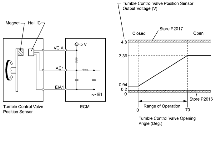
The tumble control valve position sensor is a non-contact type sensor.
The position sensor measures the opening angle of the tumble control valve. The sensor is reliable and accurate, as it is electrically controlled by Hall elements.
| DTC No. | DTC Detection Condition | Trouble Area |
|---|---|---|
| P2014 | The tumble control valve position sensor output voltage flutters up and down beyond the normal operating range (below 0.2 V or higher than 4.8 V) for more than 0.5 seconds (open or short) (1 trip detection logic). |
|
| P2016 | The tumble control valve position sensor output voltage is below 0.2 V for more than 0.5 seconds (short) (1 trip detection logic). | |
| P2017 | The tumble control valve position sensor output voltage is higher than 4.8 V for more than 0.5 seconds (open) (1 trip detection logic). |
Tech Tips
After confirming DTC P2014, P2016 or P2017, use the GTS to confirm the IAC Sensor Voltage (tumble control valve position sensor output voltage). Enter the following menus: Powertrain / Engine / Data List / All Data / IAC Sensor Voltage.
| IAC Sensor Voltage | Malfunction |
|---|---|
| 0.2 V or less |
|
| 4.8 V or higher |
|
MONITOR DESCRIPTION
The ECM IAC1 terminal voltage increases in correlation with the opening angle of the tumble control valve. When the tumble control valve is fully closed, approximately 0.94 V is applied to the IAC1 terminal. When the tumble control valve is fully open, approximately 3.39 V is applied to the IAC1 terminal.
When the output voltage of the IAC1 terminal deviates from the standard range, the ECM determines that a malfunction has occurred in the position sensor and stores a DTC.
CONFIRMATION DRIVING PATTERN
-
Connect the GTS to the DLC3.
-
Turn the ignition switch to ON and turn the GTS on.
-
Clear the DTCs (even if no DTCs are stored, perform the clear DTC procedure) Click here.
-
Turn the ignition switch off and wait for at least 30 seconds.
-
Turn the ignition switch to ON and turn the GTS on.
-
Wait 0.5 seconds or more.
-
Enter the following menus: Powertrain / Engine / Trouble Codes.
-
Read the pending DTCs.
Tech Tips
-
If a pending DTC is output, the system is malfunctioning.
-
If a pending DTC is not output, perform the following procedure.
-
-
Enter the following menus: Powertrain / Engine / Utility / All Readiness.
-
Input the DTC: P2014, P2016 or P2017.
-
Check the DTC judgment result.
GTS Display Description NORMAL
-
DTC judgment completed
-
System normal
ABNORMAL
-
DTC judgment completed
-
System abnormal
INCOMPLETE
-
DTC judgment not completed
-
Perform driving pattern after confirming DTC enabling conditions
N/A
-
Unable to perform DTC judgment
-
Number of DTCs which do not fulfill DTC preconditions has reached ECU memory limit
Tech Tips
-
If the judgment result shows NORMAL, the system is normal.
-
If the judgment result shows ABNORMAL, the system has a malfunction.
-
If the judgment result shows INCOMPLETE or N/A, perform the Confirmation Driving Pattern and check the DTC judgment result again.
-
WIRING DIAGRAM
Refer to DTC P2004 Click here.
INSPECTION PROCEDURE
Tech Tips
Read freeze frame data using the GTS. The ECM records vehicle and driving condition information as freeze frame data the moment a DTC is stored. When troubleshooting, freeze frame data can help determine if the vehicle was moving or stationary, if the engine was warmed up or not, if the air fuel ratio was lean or rich, and other data from the time the malfunction occurred.
PROCEDURE
-
PERFORM ACTIVE TEST USING GTS (OPERATE TUMBLE CONTROL VALVE)
-
Connect the GTS to the DLC3.
-
Turn the ignition switch to ON and turn the GTS on.
-
Enter the following menus: Powertrain / Engine / Active Test / Control the IAC Duty Ratio / All Data / IAC Sensor Voltage.
-
Check the output voltage of IAC Sensor Voltage while changing Control the IAC Duty Ratio from -100 to 100% (or from 100 to -100%) using the GTS.
OK The voltage output of IAC Sensor Voltage remains between 0.2 and 4.8 V while Control the IAC Duty Ratio is changed from -100 to 100% (or from 100 to -100%). HINT: Control the IAC Duty Ratio
operation
IAC Sensor Voltage
(Normal)
Suspected Trouble Area
-
IAC1 circuit shorted
-
VCIA circuit open
-
VCIA and IAC1 circuit shorted
-
IAC1 circuit open
-
EIA1 circuit open
Sensor malfunction -100% 0.2 to 1.0 V Remain below 0.2 V Remain higher than 4.8 V Other than the voltage in the 2 columns on the left 100% 3.2 to 4.8 V Remain below 0.2 V Remain higher than 4.8 V -
NG 
CHECK HARNESS AND CONNECTOR (INTAKE AIR CONTROL VALVE ACTUATOR - ECM) Click here
OK 
-
-
CHECK WHETHER DTC OUTPUT RECURS (DTC P2014, P2016 AND/OR P2017)
-
Connect the GTS to the DLC3.
-
Turn the ignition switch to ON and turn the GTS on.
-
Clear the DTCs Click here.
-
Turn the ignition switch off and wait for at least 30 seconds.
-
Turn the ignition switch to ON and turn the GTS on.
-
Drive the vehicle in accordance with the driving pattern described in the Confirmation Driving Pattern.
-
Enter the following menus: Powertrain / Engine / Trouble Codes.
-
Read the DTCs.
Result Result Proceed to DTC P2014, P2016 and/or P2017 are output A DTC is not output B
B 
CHECK FOR INTERMITTENT PROBLEMS Click here
A 
REPLACE ECM Click here
-
-
CHECK HARNESS AND CONNECTOR (INTAKE AIR CONTROL VALVE ACTUATOR - ECM)
-
Disconnect the ECM connector.
-
Disconnect the intake air control valve actuator connector.
-
Measure the resistance according to the value(s) in the table below.
Standard Resistance Tester Connection Condition Specified Condition B58-72 (VCIA) - U3-3 (VDD) Always Below 1 Ω B58-70 (IAC1) - U3-1 (OUT) Always Below 1 Ω B58-71 (EIA1) - U3-2 (GND) Always Below 1 Ω B58-72 (VCIA) or U3-3 (VDD) - Body ground Always 10 kΩ or higher B58-70 (IAC1) or U3-1 (OUT) - Body ground Always 10 kΩ or higher
NG
REPAIR OR REPLACE HARNESS OR CONNECTOR
OK
-
-
CHECK TERMINAL VOLTAGE (POWER SOURCE OF INTAKE AIR CONTROL VALVE ACTUATOR)
-
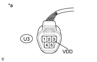
Text in Illustration *a Front view of wire harness connector
(to Intake Air Control Valve Actuator)
Disconnect the intake air control valve actuator connector.
-
Turn the ignition switch to ON.
-
Measure the voltage according to the value(s) in the table below.
Standard Voltage Tester Connection Condition Specified Condition U3-3 (VDD) - Body ground Ignition switch ON 4.5 to 5.5 V
NG
REPLACE ECM Click here
OK
-
-
REPLACE INTAKE AIR CONTROL VALVE ACTUATOR (FOR TUMBLE CONTROL VALVE)
-
Replace the intake air control valve actuator (for tumble control valve) Click here.
NEXT
-
-
CHECK WHETHER DTC OUTPUT RECURS (DTC P2014, P2016 AND/OR P2017)
-
Connect the GTS to the DLC3.
-
Turn the ignition switch to ON and turn the GTS on.
-
Clear the DTCs Click here.
-
Turn the ignition switch off and wait for at least 30 seconds.
-
Turn the ignition switch to ON and turn the GTS on.
-
Drive the vehicle in accordance with the driving pattern described in the Confirmation Driving Pattern.
-
Enter the following menus: Powertrain / Engine / Trouble Codes.
-
Read the DTCs.
Result Result Proceed to DTC P2014, P2016 and/or P2017 are output A DTC is not output B
B
END
A
REPLACE ECM Click here
-