МАСЛЯНЫЙ НАСОС СНЯТИЕ

-
DISCHARGE FUEL SYSTEM PRESSURE
-
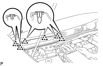
REMOVE COWL TOP VENTILATOR LOUVER RH
-
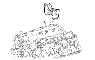
Расцепите 6 фиксаторов и снимите правую вентиляционную решетку в верхней части кожуха.
-
-
PRECAUTION
Note
After turning the engine switch off, waiting time may be required before disconnecting the cable from the battery terminal. Therefore, make sure to read the disconnecting the cable from the battery terminal notice before proceeding with work Click here.
-
DISCONNECT CABLE FROM NEGATIVE BATTERY TERMINAL
Note
When disconnecting the cable, some systems need to be initialized after the cable is reconnected Click here.
-
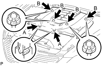
REMOVE V-BANK COVER SUB-ASSEMBLY
-
Двумя руками поднимите заднюю часть крышки, чтобы расцепить 4 фиксатора В. Сдвиньте крышку по направлению к передней части автомобиля, чтобы расцепить 2 фиксатора А, и снимите декоративную крышку V-образного двигателя.
Note
Декоративная крышка V-образного двигателя может повредиться, если поднять переднюю и заднюю часть крышки одновременно.
-
-
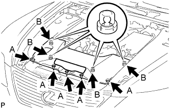
REMOVE AIR CLEANER INLET COVER SUB-ASSEMBLY
-
Снимите 5 фиксаторов, обозначенные A.
-
Поднимите крышку входного патрубка воздушного фильтра, чтобы отцепить 4 фиксатора В, и снимите крышку.
-
-
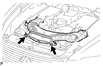
REMOVE NO. 1 AIR CLEANER INLET
-
Выверните 2 болта.
-
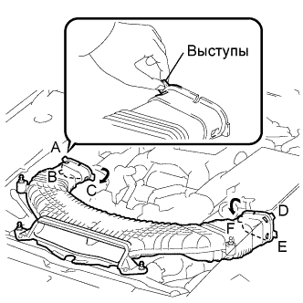
Придерживайте входной патрубок воздушного фильтра № 1 за выступы А и В и освободите соединения.
-
Поверните входной патрубок воздушного фильтра № 1, как показано на рисунке, чтобы освободить выступ С.
-
Придерживайте входной патрубок воздушного фильтра за выступы, обозначенные D и E, и освободите соединения.
-
Поверните входной патрубок воздушного фильтра № 1, как показано на рисунке, чтобы освободить выступ F.
-
-
REMOVE ENGINE ROOM SIDE COVER LH
-
Освободите 5 фиксаторов и снимите левую боковую крышку моторного отсека.
-
-
REMOVE ENGINE ROOM SIDE COVER RH
-
Снимите 5 фиксаторов и правую боковую крышку моторного отсека.
-
-
REMOVE BATTERY CLAMP SUB-ASSEMBLY
-
Remove the nut, battery clamp and 2 clamp bolts.
-
-
REMOVE BATTERY TRAY
-
Remove the battery insulator and battery.
-
Remove the 3 bolts and battery tray.
-
-
REMOVE NO. 1 ENGINE UNDER COVER
-
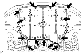
Выверните 13 винтов, освободите 7 фиксаторов и снимите защиту картера двигателя № 1.
-
-
REMOVE NO. 2 ENGINE UNDER COVER
-
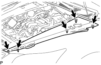
Выверните 8 болтов и снимите защиту картера двигателя № 2.
-
-
REMOVE FRONT SUSPENSION MEMBER PROTECTOR LOWER
-
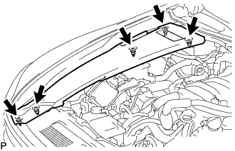
Выверните 8 болтов и снимите защиту нижнего элемента передней подвески.
-
-
REMOVE ENGINE UNDER COVER REAR LH
-
Выверните 2 винта и снимите левую заднюю защиту картера двигателя.
-
-
REMOVE ENGINE UNDER COVER REAR RH
Tech Tips
Детали с правой стороны снимаются в той же последовательности, что и с левой стороны.
-
DRAIN ENGINE OIL
-
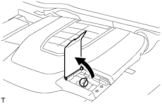
Open the oil filler cap service hole cover.
-
Remove the oil filler cap.
-
Remove the oil pan drain plug and drain the engine oil into a container.
-
Install a new gasket and the oil pan drain plug.
- Torque:
- 40 N*m { 408 kgf*cm, 30 ft.*lbf }
-
-
DRAIN ENGINE COOLANT
CAUTION:
Не снимайте пробку расширительного бачка радиатора и вентиляционную пробку, пока двигатель и радиатор не остынут. Выброс горячей охлаждающей жидкости и пара под давлением может стать причиной серьезных ожогов.
-
Ослабьте пробку сливного крана радиатора.
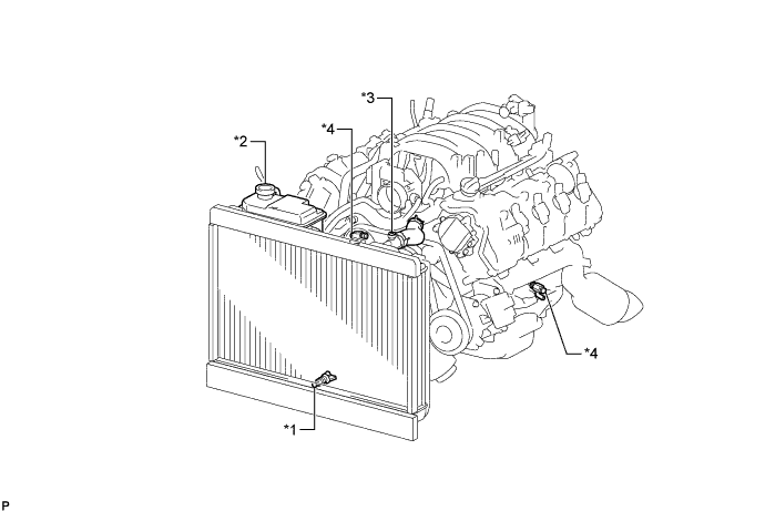
Обозначения на рисунке *1 Пробка сливного крана радиатора *2 Пробка бачка радиатора *3 Вентиляционная пробка *4 Пробка сливного крана блока цилиндров Tech Tips
Слейте охлаждающую жидкость в резервуар и утилизируйте ее в соответствии с местными требованиями.
-
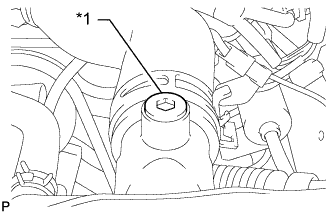
Обозначения на рисунке *1 Вентиляционная пробка Снимите пробку расширительного бачка и с помощью торцевого гаечного ключа на 6 мм снимите вентиляционную пробку.
-
Слейте охлаждающую жидкость двигателя.
-
Ослабьте 2 пробки сливного крана блока цилиндров.
-
-
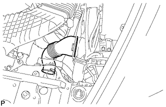
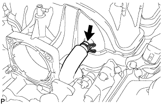
REMOVE INTAKE AIR CONNECTOR PIPE
-
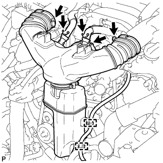
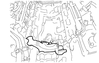
Отсоедините шланг вентиляции картера № 1 и № 2 от патрубка подачи воздуха.
-
С помощью съемника фиксаторов отсоедините 2 зажима жгута проводов.
-
Ослабьте 3 хомута и снимите патрубок подачи воздуха.
-
-
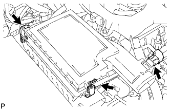
REMOVE AIR CLEANER ASSEMBLY RH
-
Disconnect the mass air flow meter connector.
-
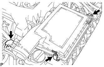
Disconnect the 2 clamps and air cleaner cap RH.
-
Remove the air cleaner element from air cleaner case RH.
-
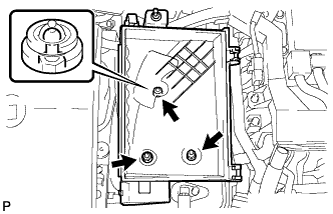
Remove the 2 nuts, clip and air cleaner case RH.
-
-
REMOVE AIR CLEANER ASSEMBLY LH
-
Disconnect the mass air flow meter connector.
-
Disconnect the 2 clamps and air cleaner cap LH.
-
Remove the air cleaner element from air cleaner case LH.
-
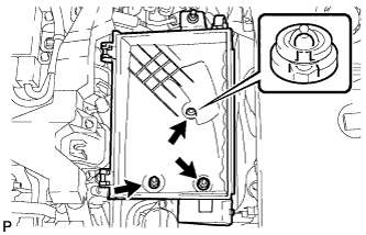
Remove the 2 nuts, clip and air cleaner case LH.
-
-
REMOVE RADIATOR RESERVOIR ASSEMBLY
-
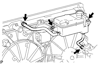
Disconnect the 2 reservoir hoses.
-
Remove the 2 bolts and radiator reservoir assembly.
-
-
REMOVE V-RIBBED BELT
-
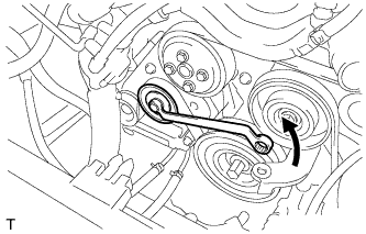
Rotate the tensioner pulley counterclockwise to loosen the belt tension.
Tech Tips
The pulley bolt for the belt tensioner has a left-handed thread.
-
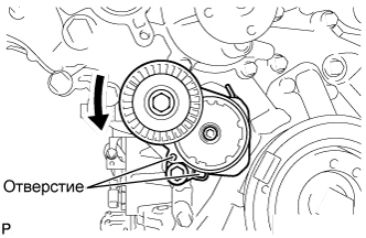
While turning the belt tensioner counterclockwise, align the holes. Insert a bar with a diameter of 5 mm (0.197 in.) into the holes to fix the belt tensioner in place.
-
-
Remove the V belt.
-
-
DISCONNECT NO. 1 RADIATOR HOSE
-
DISCONNECT NO. 2 RADIATOR HOSE
-
REMOVE ENGINE ROOM ECU OUTLET DUCT
-
Снимите выходной кабельный канал ЭБУ моторного отсека.
-
-
REMOVE SKID CONTROL ECU BRACKET
-
DISCONNECT ENGINE WIRE
-
for Engine Room LH Side:
-
Remove the ECM box cover (upper).
-
Disconnect the 3 ECT connectors and 4 ECM connectors from the ECM box.
-
Disconnect the camshaft timing control valve connector.
-
Disconnect the 4 ignition coil connectors.
-
Disconnect the 2 VVT sensor connectors.
-
Disconnect the No. 8 engine wire connector.
-
Remove the 2 bolts and disconnect the clamp and 2 clamp brackets.
-
Disconnect the engine coolant temperature sensor connector.
-
Disconnect the engine oil pressure sensor connector.
-
Disconnect the 2 camshaft timing control motor connectors. (for Bank 1)
-
Detach the clamp and disconnect the cooler compressor connector.
-
Remove the 3 bolts and disconnect the 3 clamps and ground wire.
-
Remove the bolt and clamp bracket.
-
-
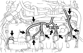
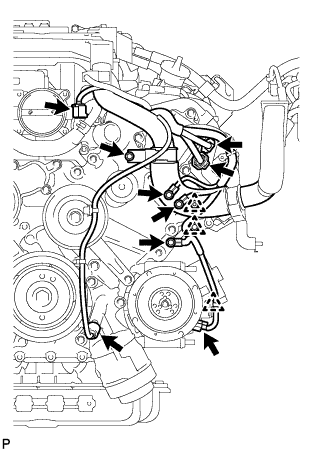
for Engine Room RH Side:
-
Detach the clamp and disconnect the 3 connectors from the front controller.
-
Remove the 2 nuts and disconnect the wires from the No. 1 engine room junction block.
-
Disconnect the camshaft timing control valve connector.
-
Disconnect the 4 ignition coil connectors.
-
Disconnect the 2 VVT sensor connectors.
-
Disconnect the engine wire connector.
-
Disconnect the 2 camshaft timing control motor connectors. (for Bank 2)
-
Disconnect the camshaft position sensor connector.
-
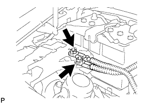
Remove the nut and disconnect the generator wire and connector.
-
Remove the nut and disconnect the starter wire and connector.
-
Disconnect the crankshaft position sensor connector.
-
Disconnect the engine oil level sensor connector.
-
Remove the 3 bolts, and disconnect the 3 clamp brackets and 2 clamps.
-
-
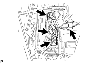
Remove the bolt and disconnect the ground wire.
-
Disconnect the No. 1 vacuum switching valve connector.
-
Disconnect the intake air control valve actuator connector.
-
Remove the 2 bolts and disconnect the 2 clamp brackets and clamp.
-
Remove the 4 nuts and disconnect the engine wire.
-
-
REMOVE FRONT EXHAUST PIPE ASSEMBLY
-
REMOVE FRONT STABILIZER BAR
-
REMOVE FRONT SUSPENSION MEMBER REINFORCEMENT LH
-
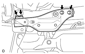
Выверните 4 болта и снимите левое усиление элемента передней подвески с автомобиля.
-
-
REMOVE STEERING SLIDING YOKE WITH SHAFT SUB-ASSEMBLY (w/ VGRS)
-
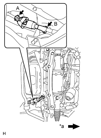
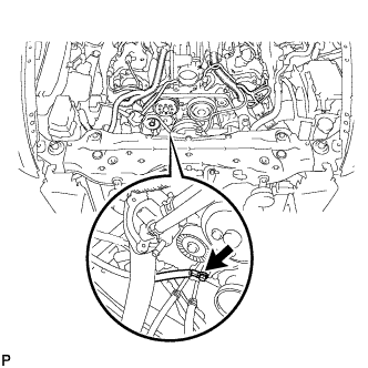
Обозначения на рисунке *a Передняя сторона автомобиля Ослабьте болт A, выверните болт B, а затем сдвиньте шлицевой хомут рулевого вала вместе с валом.
Note
-
Не выворачивайте болт A полностью.
-
Не отделяйте шлицевой хомут рулевого вала вместе с валом от тяги рулевого управления с усилителем.
-
-
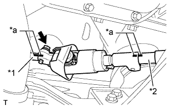
Обозначения на рисунке *1 Промежуточный вал рулевого управления № 2 *2 Тяга рулевого управления с усилителем *a Метка Нанесите метки на шлицевой хомут рулевого вала вместе с валом, промежуточный вал рулевого управления № 2 и тягу рулевого управления с усилителем.
-
Выверните болт и снимите шлицевой хомут с рулевым валом с тяги рулевого управления с усилителем в сборе.
-
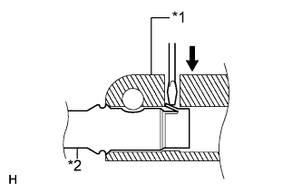
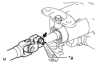
Обозначения на рисунке *1 Шлицевой хомут с рулевым валом *2 Промежуточный вал рулевого управления № 2 Отсоедините шлицевой хомут с рулевым валом от промежуточного вала рулевого управления № 2.
Tech Tips
Вставьте в отверстие хомута отвертку или аналогичный предмет. Прижмите захват промежуточного вала и снимите промежуточный вал рулевого управления № 2. Если захват поврежден, снимите его. Промежуточный вал заменять не требуется.
-
-
REMOVE STEERING SLIDING YOKE WITH SHAFT SUB-ASSEMBLY (w/o VGRS)
-
Обозначения на рисунке *a Передняя сторона автомобиля Ослабьте болт A, выверните болт B, а затем сдвиньте шлицевой хомут рулевого вала вместе с валом.
Note
-
Не выворачивайте болт A полностью.
-
Не отделяйте шлицевой хомут с рулевым валом от промежуточного вала.
-
-
Обозначения на рисунке *1 Промежуточный вал рулевого управления № 2 *2 Промежуточный вал *a Метка Нанесите метки на шлицевой хомут рулевого вала вместе с валом, промежуточный вал рулевого управления № 2 и промежуточный вал.
-
Выверните болт и снимите шлицевой хомут с рулевым валом с промежуточного вала рулевого управления.
-
Обозначения на рисунке *1 Шлицевой хомут с рулевым валом *2 Промежуточный вал рулевого управления № 2 Отсоедините шлицевой хомут с рулевым валом от промежуточного вала рулевого управления № 2.
Tech Tips
Вставьте в отверстие хомута отвертку или аналогичный предмет. Прижмите захват промежуточного вала и снимите промежуточный вал. Если захват поврежден, снимите его. Промежуточный вал заменять не требуется.
-
-
REMOVE NO. 2 STEERING INTERMEDIATE SHAFT ASSEMBLY
-
Обозначения на рисунке *a Метка Нанесите метки на промежуточный вал № 2 рулевого управления и рулевую колонку.
-
Выверните болт.
-
Снимите зажим и промежуточный вал № 2 рулевого управления.
-
-
REMOVE NO. 2 EXHAUST MANIFOLD HEAT INSULATOR
-
Disconnect the sensor connector.
-
Remove the 3 bolts and heat insulator.
-
-
REMOVE EXHAUST MANIFOLD SUB-ASSEMBLY LH
-
Remove the 8 nuts, exhaust manifold and gasket.
-
-
DISCONNECT COOLER COMPRESSOR ASSEMBLY
-
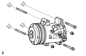
Выверните 2 болта, отверните 2 гайки, 2 резьбовые шпильки и снимите компрессор системы кондиционирования.
Tech Tips
Нет необходимости полностью снимать компрессор системы кондиционирования. Оставьте шланги подсоединенными к компрессору системы кондиционирования и подвесьте компрессор на кузове автомобиля с помощью веревки.
-
-
REMOVE ENGINE OIL LEVEL DIPSTICK GUIDE
-
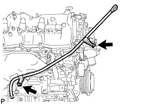
Снимите щуп проверки уровня моторного масла.
-
Выверните 2 болта и снимите трубку щупа проверки уровня моторного масла.
-
-
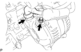
REMOVE GENERATOR ASSEMBLY
-
Отверните гайку и отсоедините жгут проводов от вывода +B.
-
Отсоедините разъем генератора.
-
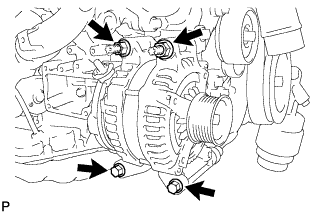
Выверните 2 болта и отверните 2 гайки.
-
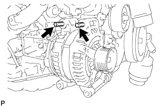
С помощью торцового ключа "TORX" E8 выверните 2 резьбовые шпильки и снимите генератор.
-
-
REMOVE WATER BY-PASS PIPE SUB-ASSEMBLY
-
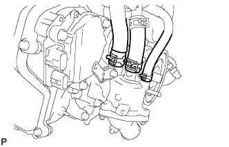
Slide the 4 clamps, and disconnect the heater water inlet hose, heater water outlet hose, water inlet hose, and No. 3 water by-pass hose from the water by-pass pipe sub-assembly.
-
Remove the 2 bolts and water by-pass pipe sub-assembly.
-
-
REMOVE INTAKE MANIFOLD
-
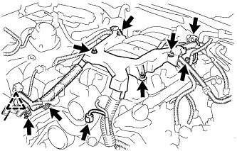
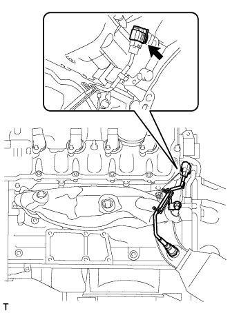
Disconnect the No. 1 ventilation hose from the intake manifold.
-
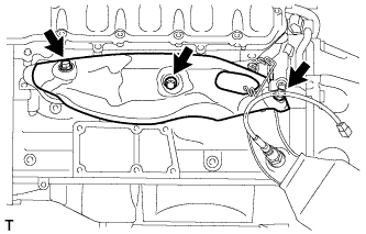
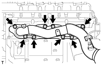
Remove the 8 bolts, 2 nuts and intake manifold.
-
Remove the 2 gaskets from the intake manifold.
-
-
REMOVE NO. 3 ENGINE COVER
-
REMOVE NO. 2 ENGINE COVER SUB-ASSEMBLY LH
-
REMOVE WATER INLET HOUSING
-
Using needle-nose pliers, grip the claws of the clips and slide the clips to disconnect the water by-pass hoses and water inlet hose.
-
Remove the 3 bolts, water inlet housing and gasket.
-
-
REMOVE WATER PUMP PULLEY
-
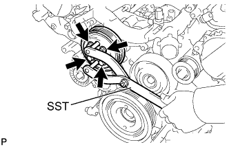
Using SST, hold the water pump pulley.
- SST
- 09960-10010 ( 09962-01000, 09963-01000 )
-
Remove the 4 bolts and water pump pulley.
-
-
REMOVE NO. 2 IDLER PULLEY SUB-ASSEMBLY
-
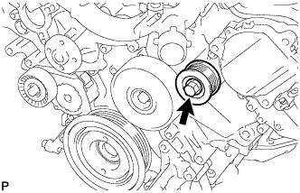
Выверните болт, снимите пластину и снимите планку и опорный ролик № 2 в сборе.
-
-
REMOVE NO. 1 IDLER PULLEY SUB-ASSEMBLY
-
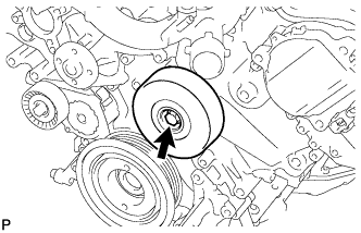
Выверните болт, снимите пластину и снимите планку и опорный ролик № 1 в сборе.
-
-
REMOVE FRONT WATER BY-PASS JOINT
-
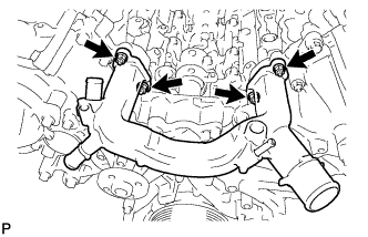
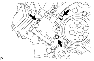
Remove the 4 nuts, water by-pass joint and 2 gaskets.
-
-
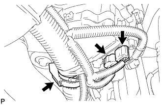
REMOVE CAMSHAFT TIMING CONTROL MOTOR ASSEMBLY LH (for Bank 1)
-
Disconnect the 2 camshaft timing control motor LH connectors and engine wire clamp.
-
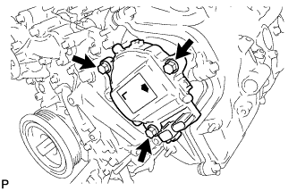
Remove the 3 bolts and camshaft timing control motor LH.
-
Remove the O-ring from the timing chain cover.
-
-
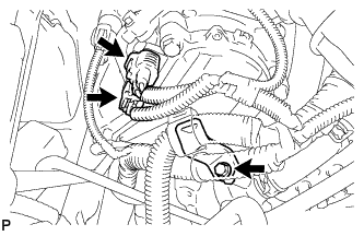
REMOVE CAMSHAFT TIMING CONTROL MOTOR ASSEMBLY (for Bank 2)
-
Disconnect the 2 camshaft timing control motor RH connectors.
-
Remove the bolt and engine wire bracket.
-
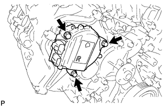
Remove the 3 bolts and camshaft timing control motor RH.
-
Remove the O-ring from the timing chain cover.
-
-
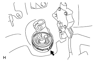
REMOVE OIL FILTER ELEMENT
-
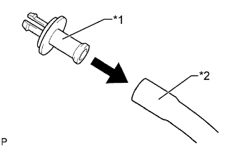
Text in Illustration *1 Pipe *2 Hose Connect a hose with an inside diameter of 15 mm (0.591 in.) to the pipe.
-
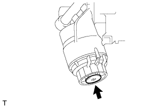
Remove the oil filter drain plug.
-
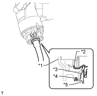
Text in Illustration *1 Oil Filter Cap *2 Valve *3 Pipe *4 O-Ring *5 Hose Install the pipe to the oil filter cap.
Note
If the O-ring is removed with the drain plug, install the O-ring together with the pipe.
Tech Tips
Use a container to catch the draining oil.
-
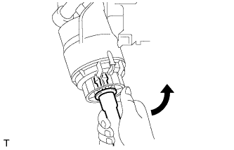
Check that oil is drained from the oil filter. Then disconnect the pipe and remove the O-ring as shown in the illustration.
-
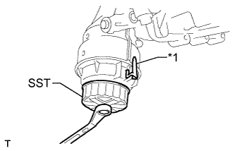
Text in Illustration *1 Oil Filter Bracket Clip Using SST, remove the oil filter cap.
- SST
- 09228-06501
Note
Do not remove the oil filter bracket clip.
-
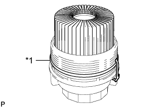
Text in Illustration *1 O-Ring Remove the oil filter element and O-ring from the oil filter cap.
Note
Be sure to remove the O-ring (for the cap) by hand, without using any tools, to prevent damage to the groove for the O-ring on the cap.
-
-
REMOVE OIL FILTER BRACKET
-
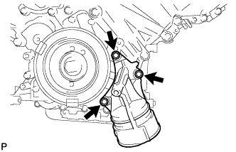
Remove the 3 bolts, filter bracket and 2 gaskets.
-
-
REMOVE RESONATOR BRACKET SUB-ASSEMBLY
-
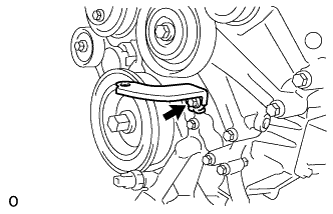
Remove the bolt and resonator bracket sub-assembly.
-
-
REMOVE CRANKSHAFT PULLEY
-
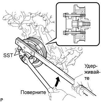
Using SST, loosen the crankshaft pulley set bolt.
- SST
- 09213-54015 ( 90119-08216 )
- 09330-00021
-
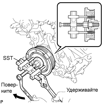
Using the pulley set bolt and SST, remove the crankshaft pulley.
- SST
- 09950-50013 ( 09951-05010, 09952-05010, 09953-05010, 09954-05010 )
-
-
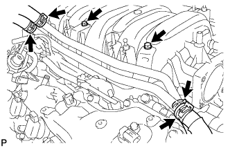
REMOVE IGNITION COIL ASSEMBLY
-
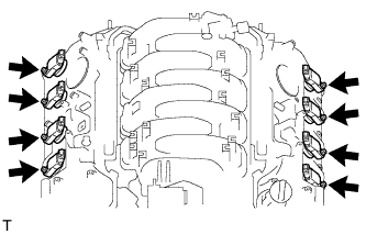
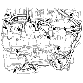
Отсоедините разъемы 8 катушек зажигания.
-
Выверните 8 болтов.
-
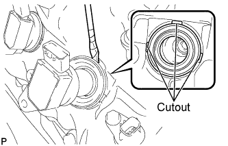
Вставьте отвертку в прорези, чтобы поддеть и снять 8 катушек зажигания с 8 прокладками трубок свечных колодцев.
Note
При снятии прокладок трубок свечных колодцев соблюдайте осторожность, чтобы не повредить крышку головки блока цилиндров.
Tech Tips
Конец отвертки перед использованием следует изолировать защитной клейкой лентой.
-
-
REMOVE CYLINDER HEAD COVER SUB-ASSEMBLY (for Bank 1)
-
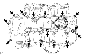
Remove the 15 bolts, 2 seal washers, cylinder head cover and gasket.
Tech Tips
Make sure the removed parts are returned to the same places they were removed from.
-
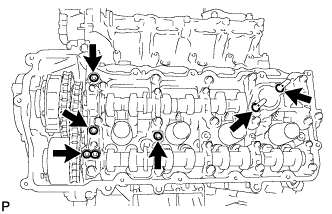
Remove the 4 gaskets and 2 O-rings from the camshaft bearing caps (No. 2, No. 3, No. 7).
-
-
REMOVE CYLINDER HEAD COVER SUB-ASSEMBLY (for Bank 2)
-
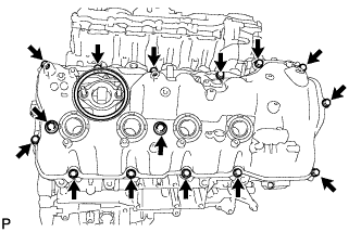
Remove the 15 bolts, 2 seal washers, cylinder head cover and gasket.
Tech Tips
Make sure the removed parts are returned to the same places they were removed from.
-
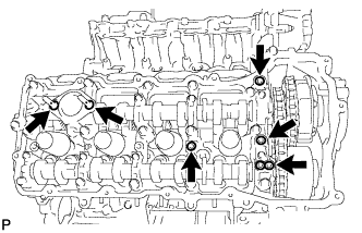
Remove the 4 gaskets and 2 O-rings from the camshaft bearing caps (No. 1, No. 3, No. 6).
-
-
REMOVE V-RIBBED BELT TENSIONER ASSEMBLY
-
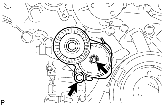
Remove the standard bolt, 6 mm hexagon wrench bolt and belt tensioner.
-
-
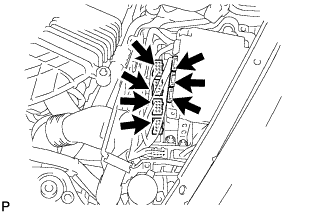
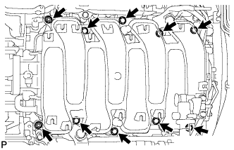
REMOVE TIMING CHAIN COVER SUB-ASSEMBLY
-
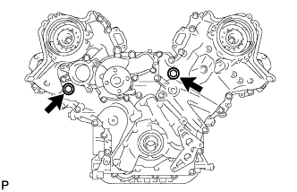
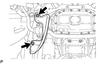
Remove the 2 plugs and 2 gaskets.
-
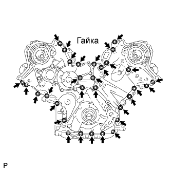
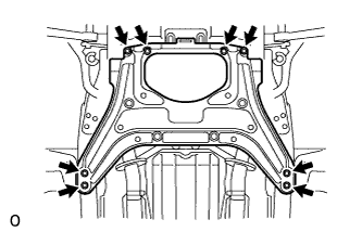
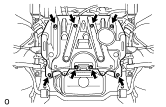
Remove the 30 bolts and nut shown in the illustration.
-
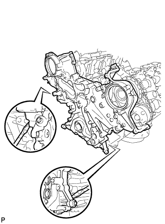
Remove the timing chain cover by prying between the timing chain cover and cylinder head and cylinder block with a screwdriver as shown in the illustration.
Note
Be careful not to damage the contact surfaces of the cylinder head, cylinder block and chain cover.
Tech Tips
Tape the screwdriver tip before use.
-
Remove the oil pump gasket from the cylinder block.
-
Remove the O-ring from the cylinder block.
-
-
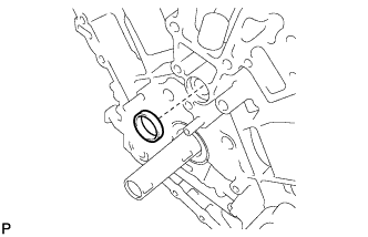
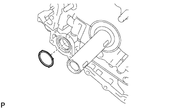
REMOVE WATER INLET PIPE
-
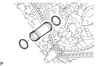
Remove the water inlet pipe.
-
Remove the 2 O-rings from the water inlet pipe.
-