КЛАПАН ПРОДУВКИ АДСОРБЕРА СНЯТИЕ
-
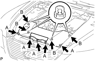
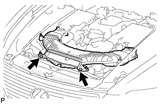
REMOVE AIR CLEANER INLET COVER SUB-ASSEMBLY
-
Снимите 5 фиксаторов, обозначенные A.
-
Поднимите крышку входного патрубка воздушного фильтра, чтобы отцепить 4 фиксатора В, и снимите крышку.
-
-
REMOVE ENGINE ROOM SIDE COVER LH
-
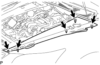
Освободите 5 фиксаторов и снимите левую боковую крышку моторного отсека.
-
-
REMOVE ENGINE ROOM SIDE COVER RH
-
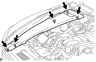
Снимите 5 фиксаторов и правую боковую крышку моторного отсека.
-
-
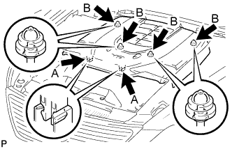
REMOVE V-BANK COVER SUB-ASSEMBLY
-
Двумя руками поднимите заднюю часть крышки, чтобы расцепить 4 фиксатора В. Сдвиньте крышку по направлению к передней части автомобиля, чтобы расцепить 2 фиксатора А, и снимите декоративную крышку V-образного двигателя.
Note
Декоративная крышка V-образного двигателя может повредиться, если поднять переднюю и заднюю часть крышки одновременно.
-
-
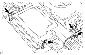
REMOVE NO. 1 AIR CLEANER INLET
-
Выверните 2 болта.
-
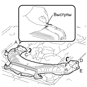
Придерживайте входной патрубок воздушного фильтра № 1 за выступы А и В и освободите соединения.
-
Поверните входной патрубок воздушного фильтра № 1, как показано на рисунке, чтобы освободить выступ С.
-
Придерживайте входной патрубок воздушного фильтра за выступы, обозначенные D и E, и освободите соединения.
-
Поверните входной патрубок воздушного фильтра № 1, как показано на рисунке, чтобы освободить выступ F.
-
-
REMOVE INTAKE AIR CONNECTOR PIPE
-
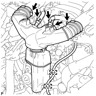
Отсоедините шланг вентиляции картера № 1 и № 2 от патрубка подачи воздуха.
-
С помощью съемника фиксаторов отсоедините 2 зажима жгута проводов.
-
Ослабьте 3 хомута и снимите патрубок подачи воздуха.
-
-
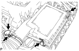
REMOVE AIR CLEANER CAP LH
-
Disconnect the mass air flow meter connector.
-
Remove the 2 clamps, loosen the hose clamp and remove the air cleaner cap LH.
-
-
REMOVE AIR CLEANER CAP RH
-
Disconnect the mass air flow meter connector.
-
Remove the 2 clamps, loosen the hose clamp and remove the air cleaner cap RH.
-
-
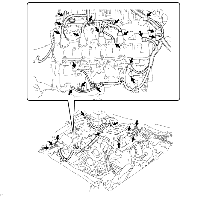
DISCONNECT ENGINE WIRE
Tech Tips
Fix the disconnected harnesses, etc. with tape or equivalent so that they do not interfere.
-
Disconnect the engine wire harness connector.
-
Remove the nut, and disconnect the +B terminal of the generator assembly.
-
Using a clip remover, disconnect the 7 engine wire harness clamps.
-
Remove the nut, and disconnect the engine wire from the fusible link block assembly.
-
Remove the 3 bolts and 3 engine wire harness clamp brackets.
-
Remove the 4 nuts, and disconnect the engine wire harness.
-
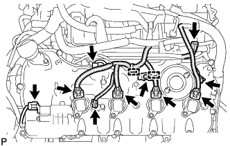
Disconnect the camshaft timing control valve connector.
-
Disconnect the 4 ignition coil connectors.
-
Disconnect the 2 VVT sensor connectors.
-
Disconnect the No. 8 engine wire connector.
-
Remove the 2 bolts and disconnect the 2 clamps and 2 clamp brackets.
-
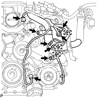
Disconnect the engine coolant temperature sensor connector.
-
Disconnect the oil pressure sensor connector.
-
Disconnect the 2 camshaft timing control motor connectors (for Bank 1).
-
Remove the 3 bolts and disconnect the 3 clamps and 3 ground wires.
-
Remove the bolt and clamp bracket.
-
Remove the bolt and disconnect the wire harness bracket.
-
Disconnect the cooler compressor connector.
-
-
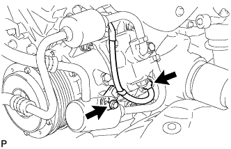
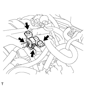
REMOVE PURGE VSV
-
Disconnect the purge VSV connector.
-
Disconnect the 2 purge line hoses from the purge VSV.
-
Remove the bolt and purge VSV.
-