ГОЛОВКА БЛОКА ЦИЛИНДРОВ ЗАМЕНА

-
REPLACE INTAKE VALVE GUIDE BUSH
-
Heat the cylinder head to approximately 80 to 100°C (176 to 212°F).
-
Place the cylinder head on wooden blocks.
-
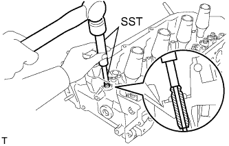
Using SST and a hammer, tap out the valve guide bush.
- SST
- 09201-10000 ( 09201-01050 )
- 09950-70010 ( 09951-07100 )
-
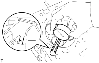
Using a caliper gauge, measure the bush bore diameter of the cylinder head side.
Standard cylinder bore diameter 10.285 to 10.306 mm (0.4049 to 0.4057 in.) If the bush bore diameter of the cylinder head is between 10.285 to 10.306 mm (0.4049 to 0.4057 in.), proceed to the next step.
If the bush bore diameter of the cylinder head is 10.356 mm (0.4077 in.) or more, replace the cylinder head.
-
Select a new guide bush (STD or O/S 0.05), and measure its diameter.
-
Machine the bush bore diameter of the cylinder head side to the diameter of the selected guide bush.
Bush bore diameter Bush Size Specified Condition STD 10.285 to 10.306 mm (0.4049 to 0.4057 in.) O/S 0.05 10.335 to 10.356 mm (0.4069 to 0.4077 in.) -
Heat the cylinder head to approximately 80 to 100°C (176 to 212°F).
-
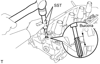
Using SST and a hammer, tap in a new guide bush to the specified protrusion height.
Standard protrusion height 14.3 to 14.7 mm (0.563 to 0.579 in.) - SST
- 09201-10000 ( 09201-01050 )
- 09950-70010 ( 09951-07100 )
-
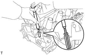
Using a sharp 5.5 mm reamer, ream the guide bush to obtain the standard specified clearance between the guide bush and valve stem.
-
-
REPLACE EXHAUST VALVE GUIDE BUSH
-
Heat the cylinder head to approximately 80 to 100°C (176 to 212°F).
-
Place the cylinder head on wooden blocks.
-
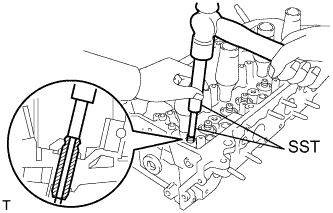
Using SST and a hammer, tap out the valve guide bush.
- SST
- 09201-10000 ( 09201-01050 )
- 09950-70010 ( 09951-07100 )
-
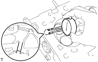
Using a caliper gauge, measure the bush bore diameter of the cylinder head.
Standard cylinder bore diameter 10.285 to 10.306 mm (0.4049 to 0.4057 in.)
-
If the bush diameter of the cylinder head is between 10.285 to 10.306 mm (0.4049 to 0.4057 in.), proceed to the next step.
-
If the bush bore diameter of the cylinder head is 10.356 mm (0.4077 in.) or more, replace the cylinder head.
-
-
Select a new guide bush (STD or O/S 0.05), and measure its diameter.
-
Machine the bush bore diameter of the cylinder head side to the diameter of the selected guide bush.
Bush bore diameter Bush Size Specified Condition STD 10.285 to 10.306 mm (0.4049 to 0.4057 in.) O/S 0.05 10.335 to 10.356 mm (0.4069 to 0.4077 in.) -
Heat the cylinder head to approximately 80 to 100°C (176 to 212°F).
-
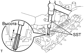
Using SST and a hammer, tap in a new guide bush to the specified protrusion height.
- SST
- 09201-10000 ( 09201-01050 )
- 09950-70010 ( 09951-07100 )
Standard protrusion height 14.3 to 14.7 mm (0.563 to 0.579 in.) -
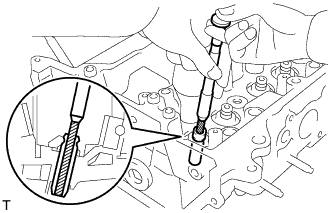
Using a sharp 5.5 mm reamer, ream the guide bush to obtain the specified clearance between the guide bush and valve stem.
-
-
REPLACE RING PIN
Note
It is not necessary to remove the ring pin unless it is being replaced.
-
Remove the ring pins.
-
Using a plastic-faced hammer, tap in new ring pins until the pin stops.
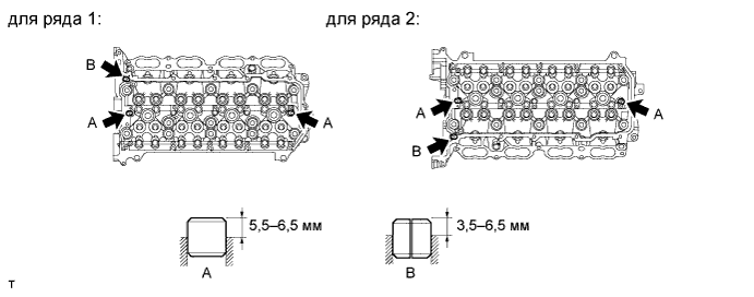
Standard protrusion Item Specified Condition Ring pin A 5.5 to 6.5 mm (0.217 to 0.256 in.) Ring pin B 3.5 to 6.5 mm (0.138 to 0.256 in.)
-
-
REPLACE STUD BOLT
Note
If a stud bolt is deformed or the threads are damaged, replace it.
-
Remove the stud bolts.
-
Using E6 and E8 "TORX" socket wrenches, install the stud bolts.
- Torque:
- 9.0 N*m { 92 kgf*cm, 80 in.*lbf, for stud bolts A, B, C and D }
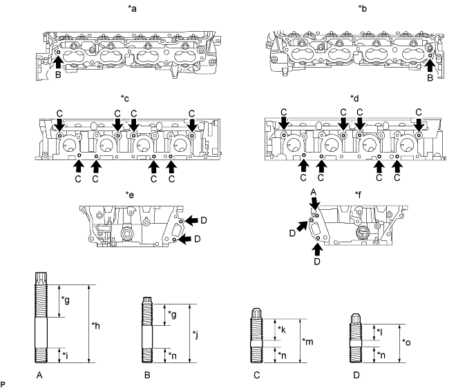
Text in Illustration *a for Bank 2 Intake Side *b for Bank 1 Intake Side *c for Bank 2 Exhaust Side *d for Bank 1 Exhaust Side *e for Bank 2 Front Side *f for Bank 1 Front Side *g 24 mm (0.945 in.) *h 52 mm (2.05 in.) *i 12 mm (0.472 in.) *j 45 mm (1.77 in.) *k 20 mm (0.787 in.) *l 14 mm (0.551 in.) *m 35 mm (1.38 in.) *n 13 mm (0.512 in.) *o 29 mm (1.14 in.) - -
-