ПРОКЛАДКА ГОЛОВКИ БЛОКА ЦИЛИНДРОВ (для ряда 2) УСТАНОВКА
-
INSPECT CYLINDER HEAD SET BOLT
-
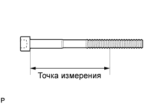
С помощью штангенциркуля измерьте минимальный диаметр удлиненного резьбового элемента в точке измерения.
Номинальный наружный диаметр 10,85-11,00 мм (0,427-0,433 дюйма) Минимально допустимый наружный диаметр 10,6 мм (0,417 дюйма) Точка замера 90 мм (3,573 дюйма) для болта со стороны впуска 85 мм (3,376 дюйма) для болта со стороны выпуска Tech Tips
-
Если при осмотре не удалось найти чрезмерно тонкие участки, проверьте центральную часть болта (см. рисунок) и найдите место с наименьшим диаметром.
-
Если диаметр меньше минимально допустимого, замените болт головки блока цилиндров.
-
-
-
INSPECT CYLINDER HEAD SUB-ASSEMBLY
-
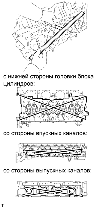
С помощью прецизионной поверочной линейки и щупа измерьте величину коробления поверхностей сопряжения на блоке цилиндров и коллекторе.
Номинальное коробление Параметр / Устройство Заданные условия С нижней стороны головки блока цилиндров 0,05 мм (0,0020 дюйма) Со стороны впускных каналов 0,08 мм (0,0031 дюйма) Со стороны выпускных каналов 0,05 мм (0,0020 дюйма) Максимально допустимая величина коробления 0,10 мм (0,0039 дюйма) Если коробление превышает максимально допустимую величину, замените головку блока цилиндров.
-
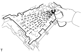
Методом цветной дефектоскопии проверьте впускные каналы, выпускные каналы и поверхность блока цилиндров на отсутствие трещин.
При обнаружении трещин замените головку блока цилиндров.
-
-
INSTALL CYLINDER HEAD SUB-ASSEMBLY (for Bank 2)
-
Check the piston protrusions for each cylinder.
-
Clean the cylinder block with solvent.
-
Set the piston of the cylinder to be measured to slightly ATDC.
-
-
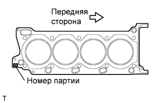
Place the cylinder head gasket on the cylinder block surface with the front face of the Lot No. stamp upward.
Note
-
Be careful of the installation direction.
-
Gently place the cylinder head in order not to damage the gasket with the bottom part of the head.
-
-
Place the cylinder head on the cylinder block.
Note
Ensure that no oil is on the mounting surface of the cylinder head.
Tech Tips
The cylinder head bolts are tightened in 3 progressive steps.
-
Apply a light coat of engine oil to the threads and under the heads of the cylinder head bolts.
-
Step 1:
-
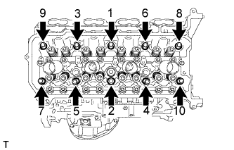
Using a 10 mm bi-hexagon wrench, install and uniformly tighten the 10 cylinder head bolts with the plate washers in several steps, in the sequence shown in the illustration.
- Torque:
- 36 N*m { 367 kgf*cm, 27 ft.*lbf }
-
-
Step 2:
-
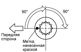
Mark the cylinder head bolt head with paint as shown in the illustration.
-
Tighten the cylinder head bolts another 90° in the sequence shown in step 1.
-
-
Step 3:
-
Tighten the cylinder head bolts by an additional 90° in the sequence shown in step 1.
-
Check that the painting marks are now facing rearward.
-
-

Uniformly install the 2 cylinder head bolts.
- Torque:
- 21 N*m { 214 kgf*cm, 15 ft.*lbf }
-
-
INSTALL VALVE STEM CAP
-
Apply a light coat of engine oil to the valve stem caps.
-
Install the 16 valve stem caps to the cylinder head.
-
-
INSTALL VALVE LASH ADJUSTER ASSEMBLY
-
Be sure to inspect the valve lash adjuster before installing it Click here.
-
Install the 16 valve lash adjusters to the cylinder head.
Note
Install the lash adjuster at the same place it was removed from.
-
-
INSTALL NO. 1 VALVE ROCKER ARM SUB-ASSEMBLY
-
Apply engine oil to the lash adjuster tips and valve stem cap ends.
-
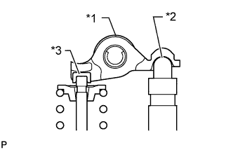
Text in Illustration *1 No. 1 Valve Rocker Arm Sub-assembly *2 Valve Lash Adjuster Assembly *3 Valve Stem Cap Make sure that the valve rocker arms are installed as shown in the illustration.
-
-
INSTALL CAMSHAFT (for Bank 2)