As the engine assembly with transmission is extremely heavy, the engine lifter may suddenly drop if the instructions listed in the repair manual are not followed. Therefore, always follow the instructions listed in the repair manual when performing this procedure.
- Click here
INSTALL IGNITION COIL
-
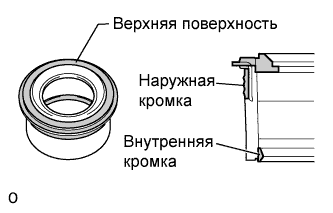
Выполните визуальный осмотр прокладки трубки свечного колодца.
Номинальное значение / Номинальный режим Участок, на котором имеется неисправность Результат проверки Верхняя поверхность Отсутствуют царапины или деформации Наружная кромка Отсутствуют царапины или деформации Внутренняя кромка Отсутствуют царапины -
Установите прокладку трубки свечного колодца на каждую катушку зажигания.
-
После установки всех прокладок трубок свечных колодцев надежно вставь все катушки зажигания.
-
Вверните 8 болтов.
10 Н*м 102 кгс*см 7 фунт-сила-футов -
Подсоедините 8 разъемов катушек зажигания.
-
-
Click here
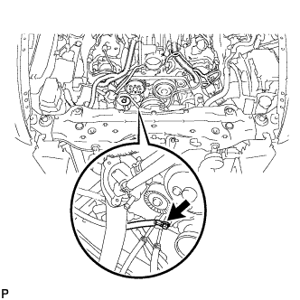
INSTALL KNOCK SENSOR
-
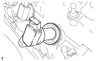
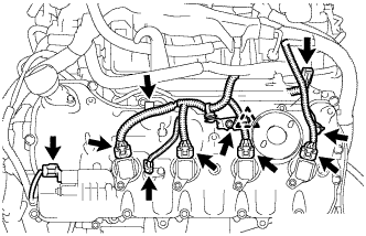
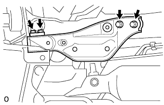
Install the 4 knock sensors with the 4 bolts so that the sensors are angled as shown in the illustration.
20 N*m 204 kgf*cm 15 ft.*lbf Note:The acceptable installation angle of the knock control sensors is between 10° upwards and downwards from the horizontal position.
-
Connect the 4 knock sensor connectors.
-
-
Click here
INSTALL ENGINE COOLANT TEMPERATURE SENSOR
-
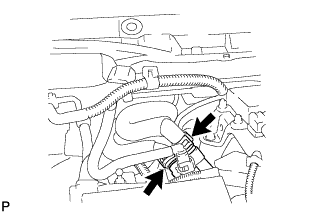
Install a new gasket to the engine coolant temperature sensor.
-
Install the engine coolant temperature sensor.
21 N*m 214 kgf*cm 15 ft.*lbf -
Connect the engine coolant temperature sensor connector.
-
- Click here
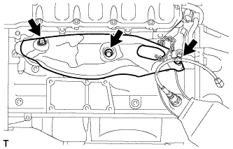
INSTALL ENGINE OIL LEVEL SENSOR
-
Install a new gasket to the engine oil level sensor.
-
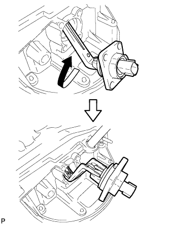
Insert the engine oil level sensor into the oil pan and rotate it 180°.
-
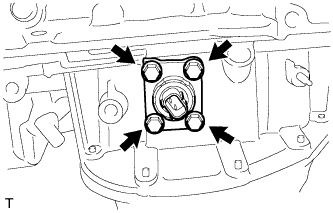
Install the engine oil level sensor with the 4 bolts.
7.0 N*m 71 kgf*cm 62 in.*lbf -
Connect the engine oil level sensor connector.
-
- Click here
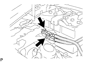
INSTALL ENGINE OIL PRESSURE SWITCH ASSEMBLY
-
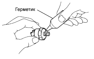
Apply adhesive to 2 or 3 threads of the switch.
Adhesive Toyota Genuine Adhesive 1344, Three Bond 1344 or equivalent -
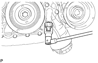
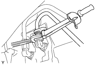
Using a 24 mm deep socket wrench, install the switch.
15 N*m 153 kgf*cm 11 ft.*lbf Note:Do not start the engine within 1 hour after installation.
-
Connect the switch connector.
-
- Click here
INSTALL WATER INLET HOUSING
-
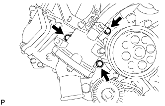
Install a new gasket to the water pump.
-
Install the water inlet housing with the 3 bolts.
21 N*m 214 kgf*cm 15 ft.*lbf
-
- Click here
INSTALL WATER PUMP PULLEY
-
Temporarily install the pulley with the 4 bolts.
-
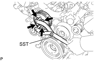
Using SST, hold the pulley and tighten the 4 bolts.
09960-10010 09962-01000 09963-01000 21 N*m 214 kgf*cm 15 ft.*lbf
-
- Click here
INSTALL NO. 1 IDLER PULLEY SUB-ASSEMBLY
-
Install the bolt and No. 1 idler pulley sub-assembly.
43 N*m 438 kgf*cm 32 ft.*lbf Tip: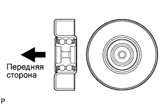
Install the No. 1 idler pulley sub-assembly in the direction shown in the illustration.
-
- Click here
INSTALL NO. 2 IDLER PULLEY SUB-ASSEMBLY
-
Install the bolt and No. 2 idler pulley sub-assembly.
43 N*m 438 kgf*cm 32 ft.*lbf
-
- Click here
INSTALL NO. 4 ENGINE COVER SUB-ASSEMBLY
-
Install the No. 4 engine cover sub-assembly.
-
- Click here
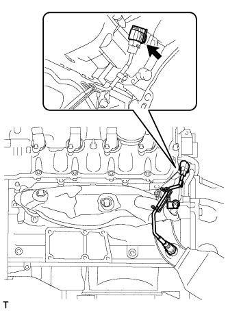
INSTALL ENGINE WIRE
-
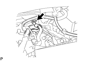
Install the engine wire with the bolt.
10 N*m 102 kgf*cm 7 ft.*lbf -
Connect the 4 knock sensor connectors.
-
-
Click here
INSTALL SEPARATOR CASE
-
Install the separator case with the 4 bolts.
10 N*m 102 kgf*cm 7 ft.*lbf
-
- Click here
INSTALL FUEL INJECTOR ASSEMBLY
-
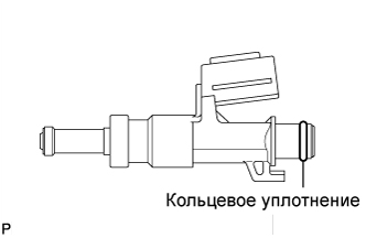
Apply gasoline to a new O-ring and install it to the injector.
Note:Check that there is no damage or foreign material in the groove of the injector when installing the injector's O-ring.
-
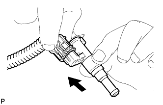
Connect the connector to the injector.
-
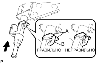
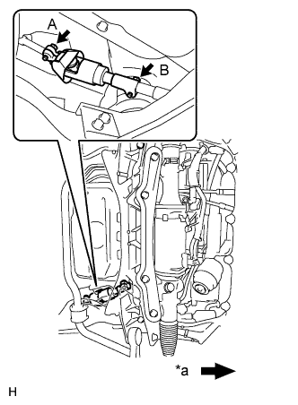
Install the injector to the delivery pipe as shown in the illustration.
Note:
-
Make sure that there are no scratches or foreign matter in or around the insertion hole of the delivery pipe.
-
When inserting the injector, be careful not to damage the O-ring.
-
Attach the part of the injector labeled B between the parts of the delivery pipe labeled A.
-
-
-
Click here
INSTALL FUEL DELIVERY PIPE
-
Connect the 4 wire harness clamps.
-
Install the 4 delivery pipe spacers and 8 insulators to the intake manifold.
-
Install the 2 delivery pipes (with injector) to the intake manifold.
-
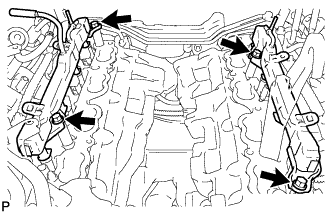
Install the 4 bolts.
21 N*m 214 kgf*cm 15 ft.*lbf Note:
Check that the part of the injector labeled B is between the parts of the delivery pipe labeled A.
-
Connect the 2 connectors.
-
- Click here
INSTALL FUEL TUBE SUB-ASSEMBLY
-
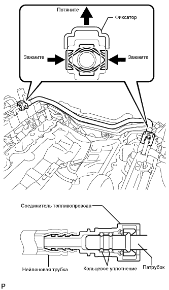
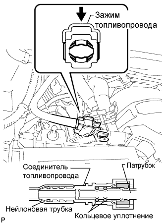
Push in the tube connector to the pipe until the tube connector makes a "click" sound.
-
Push down on the retainer to lock it in place.
Note:
-
Check that there is no damage or foreign objects on the connected part of the fuel pipe.
-
After connecting, check that the fuel tube connector and the pipe are securely connected by pulling on them.
-
-
-
Click here
INSTALL NO. 2 ENGINE COVER SUB-ASSEMBLY LH
-
Click here
INSTALL NO. 3 ENGINE COVER
- Click here
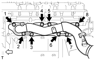
INSTALL INTAKE MANIFOLD
-
Install 2 new gaskets to the intake manifold.
-
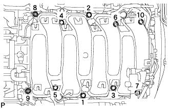
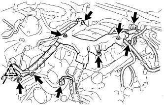
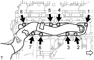
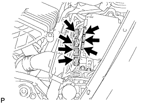
Temporarily install the intake manifold with the 2 nuts and 8 bolts. Then tighten the 2 nuts and 8 bolts uniformly in the order shown in the illustration.
21 N*m 214 kgf*cm 15 ft.*lbf -
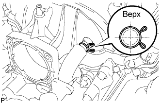
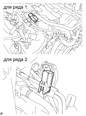
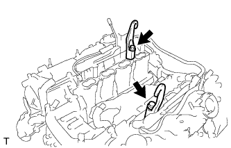
Connect the No.1 ventilation hose to the intake manifold.
Note:Face the claws of the clips as shown in the illustration.
-
- Click here
INSTALL THROTTLE BODY ASSEMBLY
-
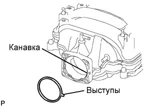
Установите на впускной коллектор новую прокладку.
-
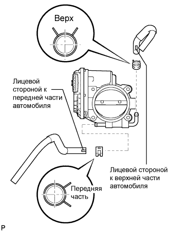
Подсоедините перепускные шланги охлаждающей жидкости № 4 и № 5 к корпусу дроссельной заслонки.
Note:Расположите захваты хомутов, как показано на рисунке.
-
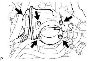
Установите корпус дроссельной заслонки и закрепите его 4 болтами.
10 Н*м 102 кгс*см 7 фунт-сила-футов -
Подсоедините разъем двигателя дроссельной заслонки.
-
- Click here
INSTALL VENTILATION HOSE
-
Click here
INSTALL WATER BY-PASS PIPE SUB-ASSEMBLY
-
Install the water by-pass pipe sub-assembly to the intake manifold with the 2 bolts.
-
Connect the heater water inlet hose, heater water outlet hose, water inlet hose, and No. 3 water by-pass hose to the water by-pass pipe sub-assembly with the 4 clamps.
Note:Face the No. 3 water by-pass hose clip as shown in the illustration.
-
- Click here
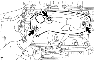
INSTALL FRONT NO. 1 ENGINE MOUNTING BRACKET RH
-
Install the front No. 1 engine mounting bracket RH with the 6 bolts.
35 N*m 357 kgf*cm 26 ft.*lbf
-
- Click here
INSTALL FRONT NO. 1 ENGINE MOUNTING BRACKET LH
-
Install the front No. 1 engine mounting bracket LH with the 6 bolts.
35 N*m 357 kgf*cm 26 ft.*lbf
-
- Click here
INSTALL ENGINE MOUNTING DAMPER
-
Install the 2 engine mounting dampers with the 2 nuts.
11 N*m 112 kgf*cm 8 ft.*lbf
-
-
Click here
INSTALL GENERATOR ASSEMBLY
-
Установите генератор и с помощью торцевого ключа "TORX" E8 заверните 2 резьбовые шпильки.
10 Н*м 102 кгс*см 7 фунт-сила-футов -
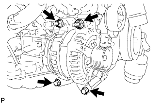
Установите генератор и закрепите 2 болтами и 2 гайками.
43 Н*м 438 кгс*см 32 фунт-сила-фута -
Подсоедините разъем генератора.
-
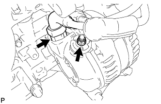
Подсоедините жгут проводов к выводу +В и закрепите его гайкой.
12 Н*м 122 кгс*см 9 фунт-сила-футов
-
- Click here
INSTALL FRONT ENGINE MOUNTING INSULATOR
Tip:Perform this procedure only when replacement of the front engine mounting insulator is necessary.
-
Install the 2 front engine mounting insulators with the 2 nuts.
70 N*m 714 kgf*cm 52 ft.*lbf
-
- Click here
INSTALL ENGINE MOUNTING SPACER
-
Install the 2 engine mounting spacers to the engine mounting insulator.
-
- Click here
INSTALL NO. 1 ENGINE HANGER
-
Установите 2 крюка для вывешивания двигателя № 1, закрепив их 2 болтами, как показано на рисунке.
43 Н*м 438 кгс*см 32 фунт-сила-фута Tip:Крюк для вывешивания двигателя № 1 12281-38150 Болт 90129-14120 -
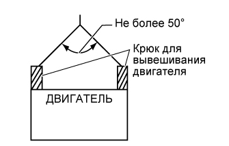
С помощью устройства для подъема двигателя и цепного блока подвесьте двигатель.
Note:Подвешивая двигатель, следите за тем, чтобы перекос двигателя, висящего на устройстве для подъема двигателя, не превысил 50°. В противном случае можно повредить двигатель или устройство для подъема двигателя.
-
- Click here
REMOVE ENGINE STAND
-
Lift the engine and remove it from the engine stand.
Note:With the exception of installing the engine assembly to an engine stand or removing the engine assembly from an engine stand, do not perform any work on the engine while it is suspended, as doing so is dangerous.
-
Place the engine onto a work bench.
-
- Click here
INSTALL FRONT SUSPENSION CROSSMEMBER SUB-ASSEMBLY
-
Install the front suspension crossmember sub-assembly with the 2 nuts.
35 N*m 357 kgf*cm 26 ft.*lbf
-
- Click here
INSTALL DRIVE PLATE AND RING GEAR SUB-ASSEMBLY
-
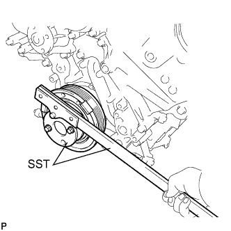
Using SST, hold the crankshaft.
09213-54015 90119-08216 09330-00021 -
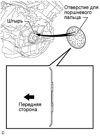
Install the crankshaft angle sensor rotor.
Tip:
-
Align the pin of the crankshaft with the pin hole of the crankshaft angle sensor rotor.
-
As the crankshaft angle sensor rotor are not reversible, be sure to install it in the direction shown in the illustration.
-
-
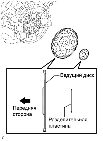
Install the drive plate and ring gear sub-assembly and spacer plate on to the crankshaft.
Tip:As the drive plate and ring gear sub-assembly and spacer plate are not reversible, be sure to install it in the direction shown in the illustration.
-
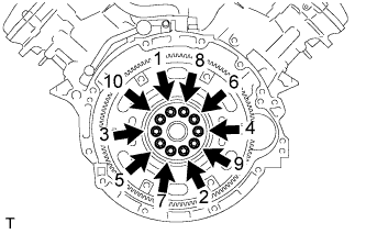
Uniformly install and tighten 10 new bolts in the sequence shown in the illustration.
30 N*m 306 kgf*cm 22 ft.*lbf Note:
-
Do not reuse the drive plate installation bolts.
-
Do not impact or damage the drive plate installation bolts. Be sure to handle them carefully.
-
-
Mark the upside of each drive plate installation bolt with paint.
-
Retighten the drive plate installation bolts by 90°.
-
Check that the painted marks are now at a 90° angle to the upside.
-
- Click here
INSTALL AUTOMATIC TRANSMISSION ASSEMBLY
-
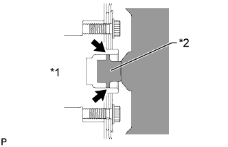
Нанесите консистентную смазку для шлицевого соединения сцепления вокруг поверхности контакта коленчатого вала с сердцевиной гидротрансформатора.
Смазка для шлицевого соединения сцепления Фирменная консистентная смазка для шлицевых соединений сцепления Clutch Spline Grease от компании Toyota или аналогичная Максимальное наносимое количество Приблизительно 1 г (0,0353 унции) Table 1. Обозначения на рисунке *1 Коленчатый вал *2 Сердцевина гидротрансформатора -
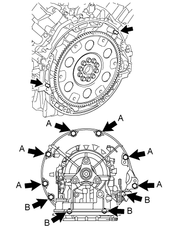
Перед установкой трансмиссии удостоверьтесь, что на поверхности блока цилиндров, вступающей в контакт с трансмиссией, закреплены 2 штифта.
Для болта A (с головкой 17 мм) 71 Н*м 724 кгс*см 52 фунт-сила-фута Для болта B (с головкой 14 мм) 37 Н*м 377 кгс*см 27 фунт-сила-футов Note:
-
Удостоверьтесь, что метка располагается, как показано на рисунке.
-
Не прилагайте чрезмерного усилия для подъема автоматической трансмиссии в сборе.
-
-
- Click here
INSTALL DRIVE PLATE AND TORQUE CONVERTER SETTING BOLT
-
Проверните коленчатый вал, чтобы обеспечить доступ к местам установки 6 установочных болтов гидротрансформатора, и, удерживая ключом болт шкива коленчатого вала, вверните каждый болт.
48 Н*м 489 кгс*см 35 фунт-сила-футов Note:Сначала вверните болт черного цвета, а затем - оставшиеся 5 болтов серебристого цвета.
-
- Click here
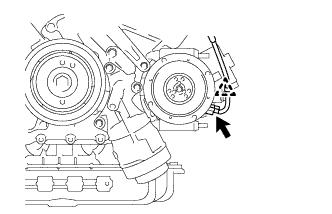
INSTALL STARTER ASSEMBLY
-
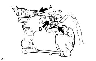
Connect the starter connector.
-
Connect the starter wire with the 2 nuts.
for nut A 10 N*m 102 kgf*cm 7 ft.*lbf for nut B 9.8 N*m 100 kgf*cm 87 in.*lbf -
Close the terminal cap.
-
Install the starter assembly with the 2 bolts.
37 N*m 377 kgf*cm 27 ft.*lbf Note: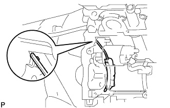
Make sure the flywheel housing side cover is as shown in the illustration.
-
- Click here
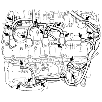
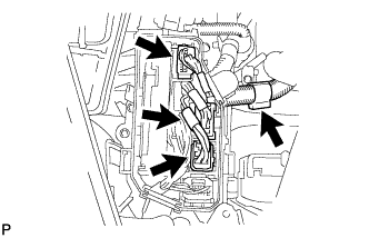
INSTALL ENGINE WIRE
-
Install the engine wire with the 4 nuts.
10 N*m 102 kgf*cm 7 ft.*lbf -
Connect the clamp and 2 clamp brackets with the 2 bolts.
10 N*m 102 kgf*cm 7 ft.*lbf -
Connect the intake air control valve actuator connector.
-
Connect the No. 1 vacuum switching valve connector.
-
Connect the throttle body connectors.
-
for Engine RH Side:
-
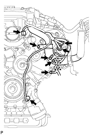
Connect the 2 clamps and install the 3 clamp brackets with the 3 bolts.
10 N*m 102 kgf*cm 7 ft.*lbf -
Connect the engine oil level sensor connector.
-
Connect the crankshaft position sensor connector.
-
Connect the starter connector and starter wire with the nut.
10 N*m 102 kgf*cm 7 ft.*lbf -
Connect the generator connector and generator wire with the nut.
12 N*m 122 kgf*cm 9 ft.*lbf -
Connect the camshaft position sensor connector.
-
Connect the engine wire connector.
-
Connect the 2 camshaft timing control motor connectors. (for Bank 2)
-
Connect the 2 VVT sensor connectors.
-
Connect the 4 ignition coil connectors.
-
Connect the camshaft timing control valve connector.
-
-
for Engine LH Side:
-
Install the clamp bracket with the bolt.
10 N*m 102 kgf*cm 7 ft.*lbf -
Connect the 3 clamps and 3 ground wires with the 3 bolts.
10 N*m 102 kgf*cm 7 ft.*lbf -
Connect the 2 camshaft timing control motor connectors. (for Bank 1)
-
Connect the oil pressure switch connector.
-
Connect the engine coolant temperature sensor connector.
-
Connect the clamp and install the 2 clamp brackets with the 2 bolts.
10 N*m 102 kgf*cm 7 ft.*lbf -
Connect the No. 8 engine wire connector.
-
Connect the 2 VVT sensor connectors.
-
Connect the 4 ignition coil connectors.
-
Connect the camshaft timing control valve connector.
-
-
- Click here
INSTALL NO. 3 EXHAUST MANIFOLD HEAT INSULATOR
-
Install the No. 3 exhaust manifold heat insulator with the 3 bolts.
10 N*m 102 kgf*cm 7 ft.*lbf
-
- Click here
INSTALL OIL COOLER TUBE
-
Временно закрепите впускной и выпускной патрубки масляного радиатора.
-
Установите 2 зажима и закрепите их 2 болтами.
5,5 Н*м 56 кгс*см 49 фунт-сила-дюймов -
С помощью разрезной головки затяните гайки впускного и выпускного патрубков масляного радиатора.
44 Н*м 450 кгс*см 33 фунт-сила-фута Note:Если совместно с динамометрическим ключом используется разрезная головка, используйте формулу для расчета заданных моментов затяжки (см. стр.Click here).
-
- Click here
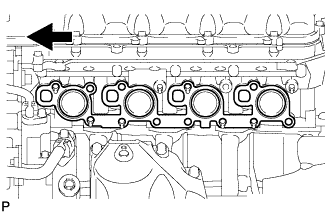
INSTALL EXHAUST MANIFOLD SUB-ASSEMBLY (for Bank 2)
-
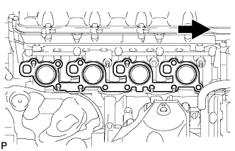
Install a new gasket as shown in the illustration.
Table 2. Text in Illustration 
Front -
Install the exhaust manifold to the cylinder head with the new 8 nuts in the order shown in the illustration.
21 N*m 214 kgf*cm 15 ft.*lbf Table 3. Text in Illustration 
Front
-
- Click here
INSTALL NO. 1 EXHAUST MANIFOLD HEAT INSULATOR
-
Install the heat insulator with the 3 bolts.
10 N*m 102 kgf*cm 7 ft.*lbf -

Connect the sensor connector.
-
- Click here
INSTALL ENGINE OIL LEVEL DIPSTICK GUIDE
-
Apply a light coat of engine oil to a new O-ring.
-
Install the new O-ring to the engine oil level dipstick guide.
-
Install the engine oil level dipstick guide with the 2 bolts.
10 N*m 102 kgf*cm 7 ft.*lbf -
Install the engine oil level dipstick.
-
- Click here
INSTALL ENGINE AND TRANSMISSION
-
Place the engine on an engine lifter.
Note:
-
Place wooden blocks or plate lift attachments so that the engine is level.
-
With the exception of installing the engine assembly to an engine stand or removing the engine assembly from an engine stand, do not perform any work on the engine while it is suspended, as doing so is dangerous.
-
Never install attachments to the oil pan of the engine assembly or transmission as doing so may deform the oil pan.
-
-
Remove the 2 bolts and 2 engine hangers.
-
Operate the engine lifter, then install the engine to the vehicle.
Note:Make sure that the engine is clear of all wiring and hoses.
-
Align the crossmember to the marks on the vehicle, and temporarily install the engine and transmission with crossmember with the 4 bolts.
Note:Make sure the crossmember is aligned to the vehicle marks as accurately as possible. If not performed accurately, the suspension alignment may become extremely misaligned.
-
Tighten the 4 bolts.
165 N*m 1683 kgf*cm 122 ft.*lbf -
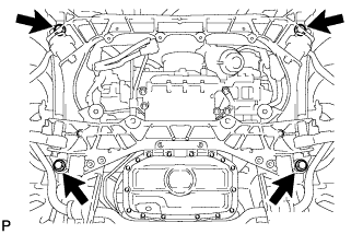
Install the 6 engine rear mounting member's bolts.
35 N*m 354 kgf*cm 26 ft.*lbf
-
- Click here
CONNECT FLOOR SHIFT GEAR SHIFTING ROD SUB-ASSEMBLY
-
Временно подсоедините тягу напольного механизма переключения передач к шарниру соединительной тяги с помощью гайки.
Tip:С номинальным моментом затяжки гайка затягивается во время регулировки положения рычага переключения передач.
-
- Click here
CONNECT FRONT NO. 2 LOWER SUSPENSION ARM ASSEMBLY
- Click here
CONNECT COOLER COMPRESSOR ASSEMBLY
-
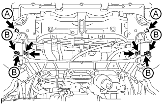
Connect the cooler compressor assembly with the 2 stud bolts, 2 nuts and 2 bolts.
for stud bolts 10 N*m 102 kgf*cm 7 ft.*lbf for nuts 25 N*m 255 kgf*cm 18 ft.*lbf for bolts 25 N*m 255 kgf*cm 18 ft.*lbf
-
- Click here
INSTALL EXHAUST MANIFOLD SUB-ASSEMBLY (for Bank 1)
-
Install a new gasket as shown in the illustration.
Table 4. Text in Illustration Front -
Install the exhaust manifold to the cylinder head with the new 8 nuts in the order shown in the illustration.
21 N*m 214 kgf*cm 15 ft.*lbf Table 5. Text in Illustration Front
-
- Click here
INSTALL NO. 2 EXHAUST MANIFOLD HEAT INSULATOR
-
Install the heat insulator with the 3 bolts.
10 N*m 102 kgf*cm 7 ft.*lbf -
Connect the sensor connector.
-
- Click here
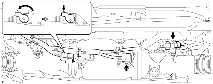
INSTALL POWER STEERING LINK ASSEMBLY (w/ VGRS)
-
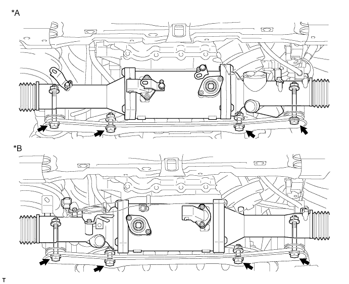
Установите тягу рулевого управления с усилителем и кронштейн кожуха рейки на переднюю раму и закрепите их 4 болтами и 4 гайками.
70 Н*м 714 кгс*см 52 фунт-сила-фута Table 6. Обозначения на рисунке *A Для моделей с левосторонним рулевым управлением *B Для моделей с правосторонним рулевым управлением -
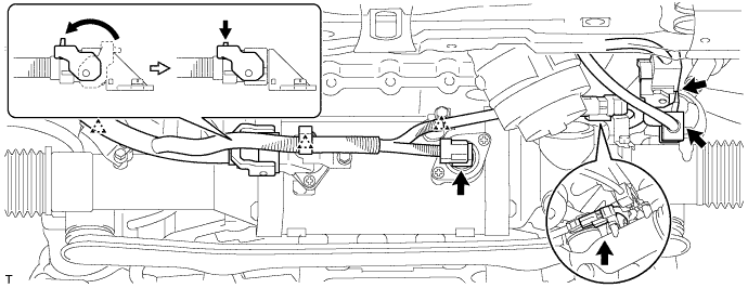
Для моделей с левосторонним рулевым управлением:
Подсоедините 5 разъемов и 3 фиксатора.
-
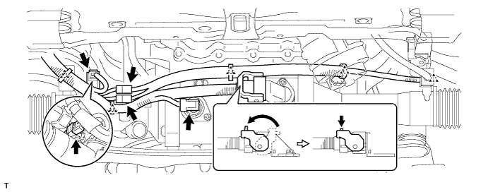
Для моделей с правосторонним рулевым управлением:
Подсоедините 5 разъемов и 5 фиксаторов.
-
- Click here
INSTALL POWER STEERING LINK ASSEMBLY (w/o VGRS)
-
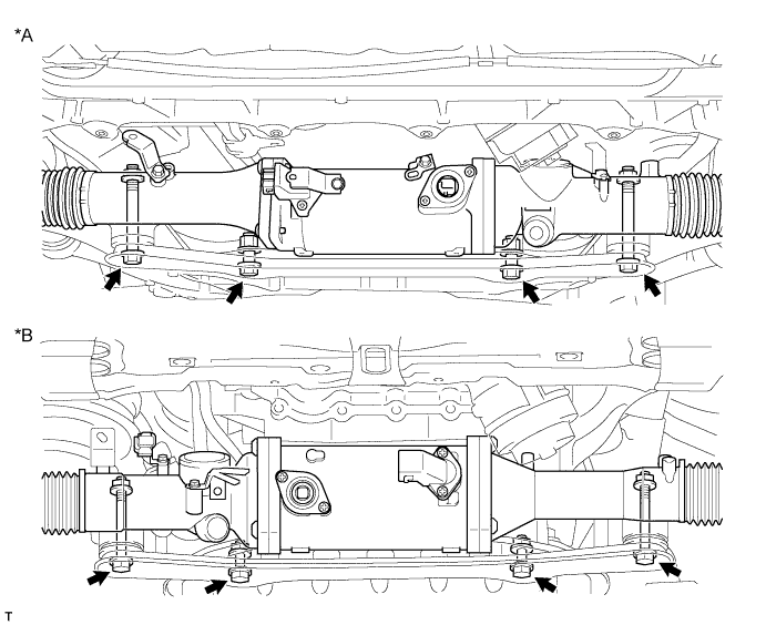
Установите тягу рулевого управления с усилителем и кронштейн кожуха рейки на переднюю раму и закрепите их 4 болтами и 4 гайками.
70 Н*м 714 кгс*см 52 фунт-сила-фута Table 7. Обозначения на рисунке *A Для моделей с левосторонним рулевым управлением *B Для моделей с правосторонним рулевым управлением -
Для моделей с левосторонним рулевым управлением:
Подсоедините 3 разъема и закрепите 3 фиксатора.
-
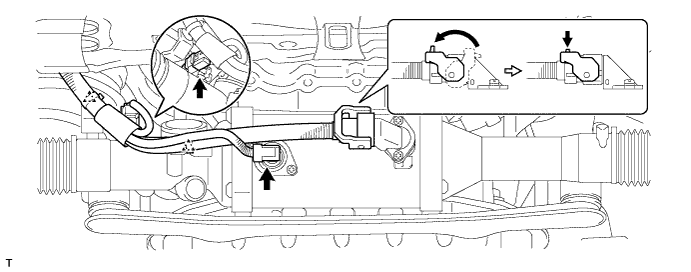
Для моделей с правосторонним рулевым управлением:
Подсоедините 3 разъема и закрепите 2 фиксатора.
-
- Click here
INSTALL NO. 2 STEERING INTERMEDIATE SHAFT ASSEMBLY
-
Установите зажим на чехол выходного отверстия рулевой колонки.
-
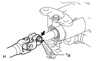
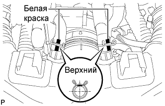
Совместите метки на промежуточном валу № 2 рулевого управления и рулевой колонке.
Table 8. Обозначения на рисунке *a Метка -
Вверните болт.
35 Н*м 360 кгс*см 26 фунт-сила-футов
-
- Click here
INSTALL STEERING SLIDING YOKE WITH SHAFT SUB-ASSEMBLY (w/ VGRS)
-
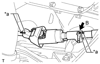
Совместите метки на промежуточном валу рулевого управления № 2 в сборе и шлицевом хомуте рулевого вала в сборе.
Table 9. Обозначения на рисунке *a Метка -
Совместите сборочные метки на шлицевом хомуте рулевого вала и тяге рулевого управления с усилителем.
-
Не затягивая, вверните болт B.
Note:Не затягивайте болт.
-
Вверните болт A и затяните болт B.
35 Н*м 360 кгс*см 26 фунт-сила-футов Table 10. Обозначения на рисунке *a Передняя сторона автомобиля
-
- Click here
INSTALL STEERING SLIDING YOKE WITH SHAFT SUB-ASSEMBLY (w/o VGRS)
-
Совместите метки на промежуточном валу рулевого управления № 2 и шлицевом хомуте рулевого вала в сборе.
Table 11. Обозначения на рисунке *a Метка -
Совместите сборочные метки на шлицевом хомуте рулевого вала и промежуточном валу рулевого управления.
-
Не затягивая, вверните болт B.
Note:Не затягивайте болт.
-
Вверните болт A и затяните болт B.
35 Н*м 360 кгс*см 26 фунт-сила-футов Table 12. Обозначения на рисунке *a Передняя сторона автомобиля
-
- Click here
INSTALL FRONT SUSPENSION MEMBER REINFORCEMENT LH
-
Установите левое усиление элемента передней подвески на автомобиль и закрепите его 4 болтами.
50 Н*м 510 кгс*см 37 фунт-сила-дюймов
-
- Click here
INSTALL FRONT SUSPENSION MEMBER REINFORCEMENT RH
Tip:Детали с правой стороны устанавливаются в той же последовательности, что и с левой стороны.
- Click here
INSTALL FRONT STABILIZER BAR
- Click here
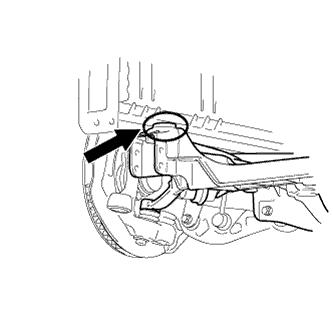
INSTALL PROPELLER WITH CENTER BEARING SHAFT ASSEMBLY
- Click here
INSTALL NO. 1 EXHAUST PIPE SUPPORT BRACKET SUB-ASSEMBLY
-
Установите кронштейн опоры выпускной трубы № 1 в сборе и закрепите его 2 болтами.
43 Н*м 438 кгс*см 32 фунт-сила-фута
-
- Click here
INSTALL FRONT EXHAUST PIPE ASSEMBLY
- Click here
CONNECT HOSES AND CONNECTORS
-
Connect the purge line hose.
-
Connect the 2 heater hoses.
-
Connect the wires with No. 1 engine room junction block with the 2 nuts.
13 N*m 133 kgf*cm 10 ft.*lbf -
Connect the ground wire with the bolt.
21 N*m 214 kgf*cm 15 ft.*lbf -
Connect the 3 connectors with front controller with the clamp.
-
Attach the clamp and connect the cooler compressor connector.
-
Connect the 3 TCM connectors and 4 ECM connectors.
-
Install the ECM box cover (upper).
-
- Click here
CONNECT NO. 3 FUEL HOSE
-
Push in the tube connector to the pipe until the tube connector makes a "click" sound.
-
Install the fuel pipe clamp.
Note:
-
Check that there is no damage or foreign objects on the connected part of the fuel pipe.
-
After connecting, check that the fuel tube connector and the pipe are securely connected by pulling on them.
-
-
- Click here
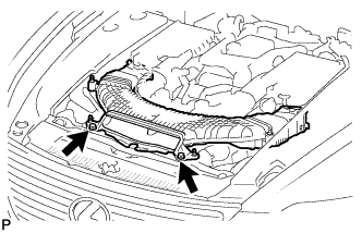
INSTALL ENGINE ROOM ECU OUTLET DUCT
-
Install the engine room ECU outlet duct.
-
- Click here
CONNECT NO. 2 RADIATOR HOSE
- Click here
CONNECT NO. 1 RADIATOR HOSE
-
Click here
INSTALL AIR CLEANER ASSEMBLY RH
-
Install the air cleaner case RH with the 2 nuts and clip.
5.0 N*m 51 kgf*cm 44 in.*lbf -
Install the air cleaner element to the air cleaner case RH.
-
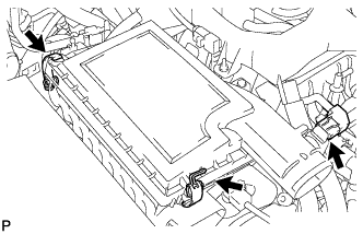
Install the air cleaner cap RH with the 2 clamps.
-
Connect the mass air flow meter connector.
-
-
Click here
INSTALL AIR CLEANER ASSEMBLY LH
-
Install the air cleaner case LH with the 2 nuts and clip.
5.0 N*m 51 kgf*cm 44 in.*lbf -
Install the air cleaner element to the air cleaner case LH.
-
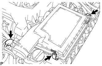
Install the air cleaner cap LH with the 2 clamps.
-
Connect the mass air flow meter connector.
-
- Click here
INSTALL V-RIBBED BELT
-
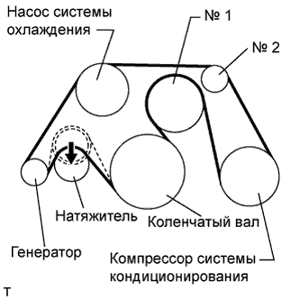
Install the V belt as shown in the illustration.
Note:Check that the drive belt is properly set to each pulley.
-
Rotate the tensioner pulley counterclockwise, and then remove the fix bar.
-
-
- Click here
INSTALL INTAKE AIR CONNECTOR PIPE
-
Совместите выступ на резонаторе воздухозаборника с вырезом кронштейна и вставьте выступ.
-
Установите патрубок подачи воздуха и закрепите 3 хомутами.
для патрубка подачи воздуха и корпуса дроссельной заслонки 4,8 Н*м 49 кгс*см 42 фунт-сила-дюйма для патрубка подачи воздуха и крышки воздушного фильтра 3,8 Н*м 39 кгс*см 34 фунт-сила-дюйма Tip:
-
Вставьте выступ на патрубке подачи воздуха в отверстие хомута.
-
Патрубок подачи воздуха и хомут корпуса дроссельной заслонки могут быть затянуты с моментом из диапазона 4,0-5,5 Н*м (41-56 кгс*см, 35-49 фунт-сила-дюймов), а патрубок подачи воздуха и хомут крышки воздушного фильтра – с моментом из диапазона 2,0-5,5 Н*м (20-56 кгс*см, 18-49 фунт-сила-дюймов).
-
-
Установите 2 зажима жгута проводов.
-
Подсоедините шланг вентиляции картера № 1 и № 2 к патрубку подачи воздуха.
Tip:
-
Расположите захваты хомутов, как показано на рисунке.
-
Установите хомуты так, чтобы они находились в пределах меток, нанесенных на шланге краской.
-
-
-
Click here
INSTALL NO. 1 AIR CLEANER INLET
-
Совместите отверстия с местами соединений A и подсоедините входной патрубок воздушного фильтра № 1.
-
Установите входной патрубок воздушного фильтра № 1 и закрепите его 2 болтами.
5,0 Н*м 51 кгс*см 44 фунт-сила-дюйма
-
- Click here
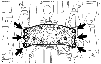
INSTALL REAR FRAME SIDE RAIL
-
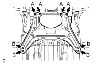
Install the 2 rear frame side rails with the 6 bolts and 4 nuts.
for bolt A 30 N*m 306 kgf*cm 22 ft.*lbf for nut B 44 N*m 453 kgf*cm 33 ft.*lbf
-
- Click here
INSTALL FRONT SUSPENSION LOWER CROSSMEMBER
-
Установите нижний подрамник передней подвески и закрепите его 4 болтами.
25 Н*м 255 кгс*см 18 фунт-сила-футов -
Установите 2 фиксатора.
-
- Click here
INSTALL FRONT BUMPER COVER
- Click here
CONNECT NO. 1 OIL COOLER OUTLET HOSE
-
Подсоедините выпускной патрубок масляного радиатора № 1 к радиатору.
-
- Click here
CONNECT NO. 1 OIL COOLER INLET HOSE
-
Подсоедините впускной патрубок масляного радиатора № 1 к радиатору в сборе.
-
- Click here
ADD ENGINE OIL
-
Add fresh oil.
Standard engine oil Oil grade Oil Viscosity (SAE) API grade SL "energy-conserving", SM "energy-conserving", SN "resource-conserving" or ILSAC multigrade engine oil 0W-20
5W-20
5W-30
10W-30
API grade SL, SM or SN multigrade engine oil 15W-40
20W-50
Standard capacity Item Specified Condition Drain and refill without oil filter change 8.4 liters (8.9 US qts, 7.4 Imp. qts) Drain and refill with oil filter change 8.6 liters (9.1 US qts, 7.6 Imp. qts) Dry fill 10.2 liters (10.8 US qts, 9.0 Imp. qts) -
Install the oil filler cap.
-
Close the oil filler cap service hole cover.
-
- Click here
ADD ENGINE COOLANT
Общая емкость 11,8 литра (12,5 кварты США, 10,4 английской кварты) CAUTION:Не снимайте пробку расширительного бачка радиатора, пока двигатель и радиатор не остынут. Выброс горячей охлаждающей жидкости и пара под давлением может стать причиной серьезных ожогов.
Note:Перед добавлением охлаждающей жидкости установите выключатель системы кондиционирования в положение OFF (ВЫКЛ).
-
Затяните пробку сливного крана радиатора.
-
Затяните 2 пробки сливных кранов блока цилиндров.
13 Н*м 133 кгс*см 10 фунт-сила-футов -
Долейте в расширительный бачок радиатора фирменную жидкость с увеличенным сроком замены (SLLC) от компании Тойота.
Объем Приблизительно 5,0 литра (5,3 кварты США, 4,4 английской кварты) Tip:
-
Автомобили Тойота охлаждающей жидкостью TOYOTA SLLC на заводе. Во избежание повреждения системы охлаждения двигателя или других технических проблем разрешается использовать только охлаждающую жидкость "TOYOTA Super Long Life Coolant" или аналогичную высококачественную охлаждающую жидкость на основе этиленгликоля (а не на силикатной, аминовой, нитритной или борнокислой основе), изготовленную по гибридной технологии органических кислот с длительным сроком годности (охлаждающая жидкость, изготовленная по гибридной технологии органических кислот, состоит из низкофосфатных соединений и органических кислот).
-
Обратитесь к уполномоченному дилеру Toyota, в ремонтную мастерскую или к квалифицированному специалисту с необходимым оборудованием за подробной информацией.
-
Время открывания термостата можно проверить, сжав входной патрубок радиатора рукой и убедившись, что охлаждающая жидкость поступает в шланг.
-
-
Затем долейте охлаждающую жидкость в бачок радиатора до отметки "FULL".
-
Несколько раз сожмите рукой патрубки радиатора № 1 и № 2, затем проверьте уровень охлаждающей жидкости.
Если уровень охлаждающей жидкости недостаточен, добавьте жидкость.
-
С помощью торцевого шестигранного ключа на 6 мм установите вентиляционную пробку.
1,5 Н*м 15 кгс*см 13 фунт-сила-дюймов -
Выпустите воздух из системы охлаждения.
Note:Перед запуском двигателя для прогрева установите выключатель системы кондиционирования в положение OFF (ВЫКЛ).
-
При двигателе, работающем на холостом ходу в течение приблизительно 10 минут, убедитесь, что уровень хладагента остается на отметке "FULL", при необходимости добавляя охлаждающую жидкость.
-
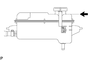
Дав двигателю поработать на холостом ходу в течение 10 минут, долейте охлаждающую жидкость до линии B.
Объем Приблизительно 2,5-3,5 л (2,6-3,7 кварты США, 2,2-3,1 английской кварты) Table 13. Обозначения на рисунке Линия B Tip:Линия В находится в нижней внутренней части наливной горловины.
-
Закройте пробку расширительного бачка радиатора и поддерживайте частоту вращения коленчатого вала двигателя в диапазоне 1500-2000 об/мин в течение 5 минут.
CAUTION:
-
Работайте в защитных перчатках.
-
Будьте осторожны: патрубок радиатора горячий.
-
Не прикасайтесь к вентиляторам радиатора.
Tip:Время открывания термостата можно проверить, сжав шланг радиатора № 1 рукой и убедившись, что SLLC поступает в шланг.
-
-
-
Остановите двигатель и подождите, пока охлаждающая жидкость остынет до температуры окружающего воздуха.
-
Проверьте уровень охлаждающей жидкости.
Если уровень охлаждающей жидкости ниже уровня "FULL", добавьте охлаждающую жидкость до отметки "FULL".
-
- Click here
ADD AUTOMATIC TRANSMISSION FLUID
- Click here
CONNECT CABLE TO NEGATIVE BATTERY TERMINAL
Note:When disconnecting the cable, some systems need to be initialized after the cable is reconnected (Click here).
- Click here
INSPECT FOR OIL LEAK
-
Start the engine. Make sure that there are no oil leaks from the area that was worked on.
-
- Click here
INSPECT FOR COOLANT LEAK
CAUTION:Do not remove the radiator reservoir cap while the engine and radiator are still hot. Pressurized, hot engine coolant and steam may be released and cause serious burns.
Note:Before each inspection, turn the A/C switch OFF.
-
Fill the radiator with coolant and attach a radiator cap tester.
-
Warm up the engine.
-
Using the radiator cap tester, increase the pressure inside the radiator to 118 kPa (1.2 kgf/cm2, 17 psi), and check that the pressure does not drop.
If the pressure drops, check the hoses, radiator and water pump for leaks. If no external leaks are found, check the heater core, cylinder block and head.
-
- Click here
INSPECT FOR FUEL LEAK
-
Connect the intelligent tester to the DLC3.
-
Turn the engine switch on (IG).
Note:Do not start the engine.
-
Turn the intelligent tester on.
-
Select the following menus: Powertrain / Engine / Active Test / Control the Fuel Pump / Speed.
-
Check the fuel pump operation.
-
Check for pressure in the fuel inlet tube from the fuel line. Check that the sound of fuel flowing in the fuel tank can be heard.
If no sound can be heard, check the integration relay, fuel pump, ECM and wiring connector.
-
-
Check for fuel leaks.
-
Check that there are no fuel leaks anywhere on the system after performing maintenance.
If there is a fuel leak, repair or replace parts as necessary.
-
-
- Click here
INSPECT FOR EXHAUST GAS LEAK
-
При наличии утечки газа затяните соединения в местах утечки. При необходимости замените поврежденные детали.
-
- Click here
PLACE FRONT WHEELS FACING STRAIGHT AHEAD
- Click here
CHECK AND ADJUST FRONT WHEEL ALIGNMENT
- Click here
CHECK SHIFT LEVER POSITION
(см. стр.Click here)
- Click here
INSTALL FRONT SUSPENSION MEMBER PROTECTOR LOWER
-
Install the front suspension member protector lower with the 8 bolts.
5.5 N*m 56 kgf*cm 49 in.*lbf
-
- Click here
INSTALL NO. 2 ENGINE UNDER COVER
-
Install the No. 2 engine under cover with the 8 bolts.
for Bolt A 10 N*m 102 kgf*cm 7 ft.*lbf for Bolt B 27 N*m 275 kgf*cm 20 ft.*lbf
-
- Click here
INSTALL NO. 1 ENGINE UNDER COVER
-
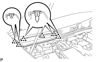
Установите защиту картера двигателя № 1 и закрепите ее 13 винтами и 7 фиксаторами.
-
- Click here
CHECK IGNITION TIMING
-
Warm up and stop the engine.
Tip:A warmed up engine should have an engine coolant temperature of over 80°C (176°F) and an engine oil temperature of 60°C (140°F), and the engine rpm should be stabilized.
-
When using the intelligent tester:
-
Connect the intelligent tester to the DLC3.
-
Start the engine and idle it.
-
Push the intelligent tester main switch on.
-
Enter the following items: Powertrain / Engine and ECT / Data List / Primary / IGN Advance /
Standard ignition timing 8 to 18° BTDC @ idle Tip:Refer to the intelligent tester operator's manual for further details.
-
-
When not using the intelligent tester:
-
Remove the V-bank cover.
-
Remove the 5 clips and air cleaner inlet cover.
-
Remove the 5 clips and engine room side cover LH.
-
Remove the 2 bolts and No. 1 air cleaner inlet.
-
Disconnect the air cleaner cap LH.
-
Remove the 2 nuts and air cleaner case LH.
-
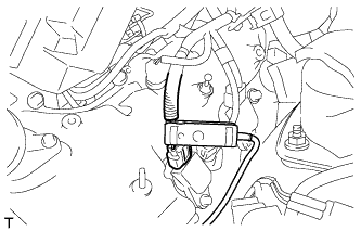
Connect the tester probe of a timing light to the wire of the ignition connector for No. 1 cylinder.
Note:Use a timing light that detects primary signals.
-
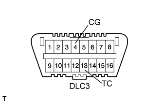
Using SST, connect terminals 13 (TC) and 4 (CG) of the DLC3.
09843-18040 Note:
-
Confirm the terminal numbers before connecting them. Connecting the wrong terminals can damage the engine.
-
When checking the ignition timing, the transmission should be in neutral.
-
-
Using a timing light, check the ignition timing.
Standard ignition timing 8 to 12° BTDC @ idle -
Remove SST from the DLC3.
-
Check the ignition timing.
Standard ignition timing 8 to 18° BTDC @ idle -
Check that the ignition timing advances immediately when the engine speed is increased.
-
Disconnect the timing light from the engine.
-
Install the air cleaner case LH with the 2 nuts.
5.0 N*m 51 kgf*cm 44 in.*lbf -
Connect the air cleaner cap LH.
-
Install the No. 1 air cleaner inlet with the 2 bolts.
5.0 N*m 51 kgf*cm 44 in.*lbf -
Install the engine room side cover LH with the 5 clips.
-
Install the air cleaner inlet cover with the 5 clips.
-
Install the V-bank cover.
-
-
- Click here
CHECK IDLE SPEED
-
Warm up and stop the engine.
Tip:A warmed up engine should have an engine coolant temperature of over 80°C (176°F) and an engine oil temperature of 60°C (140°F), and the engine rpm should be stabilized.
-
When using the intelligent tester:
-
Connect the intelligent tester to the DLC3.
Note:Switch off all accessories and the A/C before connecting the intelligent tester.
-
Race the engine speed at 2500 rpm for approximately 90 seconds.
-
Push the intelligent tester main switch on.
-
Enter the following items: Powertrain / Engine and ECT / Data List / Primary / Engine Speed /
Standard idle speed 700 to 800 rpm Note:When checking the idle speed, the transmission should be in neutral.
Tip:Refer to the intelligent tester operator's manual for further details.
If the idle speed is not as specified, check the air intake system.
-
Disconnect the intelligent tester from the DLC3.
-
-
When not using the intelligent tester:
-
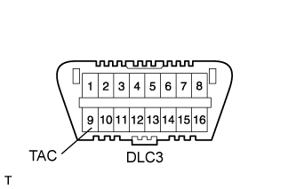
Using SST, connect a tachometer probe to terminal 9 (TAC) of the DLC3.
09843-18030 Note:Confirm the terminal numbers before connecting them. Connecting the wrong terminals can damage the engine.
-
Race the engine speed at 2500 rpm for approximately 90 seconds.
-
Check the idle speed.
Idle speed (Transmission neutral position) 700 to 800 rpm If the speed is not as specified, check the air intake system.
-
Disconnect the tachometer from the DLC3.
-
-
- Click here
CHECK CO/HC
Tip:This check determines whether or not the idle CO/HC complies with regulations.
-
Start the engine.
-
Keep the engine speed at 2500 rpm for approximately 180 seconds.
-
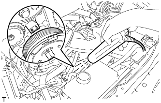
Insert the CO/HC meter testing probe at least 40 cm (1.31 ft) into the tailpipe during idling.
-
Immediately check CO/HC concentration at idle and 2500 rpm.
Tip:
-
When performing the 2 mode (2500 rpm and idle) test, follow the measurement order prescribed by the applicable local regulations.
-
If the CO/HC concentration does not comply with regulations, troubleshoot in the order given below.
-
Check the heated oxygen sensor (for Sensor 1) (Click here) and heated oxygen sensor (for Sensor 2) (Click here) operation.
-
See the table below for possible causes, then inspect and correct the applicable causes if necessary.
CO HC Symptom Causes Normal High Rough idle
-
1. Faulty ignitions
-
-
Incorrect timing
-
Plugs are contaminated, shorted, or gaps are defective.
-
-
2. Leaky intake and exhaust valves
-
3. Leaky cylinder
Low High Rough idle
(Fluctuating HC reading)
-
1. Vacuum leaks
-
-
PCV hose
-
Intake manifold
-
Throttle body
-
-
2. Lean mixture causing misfire
High High Rough idle
(Black smoke from exhaust)
-
1. Restricted air filter
-
2. Faulty SFI system
-
-
Faulty pressure
-
Defective engine coolant temperature sensor
-
Faulty ECM
-
Faulty injector
-
Faulty throttle position sensor
-
Faulty mass air flow meter
-
-
-
-
- Click here
CHECK ENGINE OIL LEVEL
-
Warm up the engine, stop the engine and wait 5 minutes. The oil level should be between the dipstick's low level mark and full level mark.
If low, check for leakage and add oil up to the full level mark.
Note:Do not fill engine oil above the full level mark.
Tip:A certain amount of engine oil will be consumed while driving. In the following situations, oil consumption may increase, and engine oil may need to be refilled in between oil maintenance intervals.
-
When the engine is new, for example directly after purchasing the vehicle or after replacing the engine.
-
If low quality oil or oil of an inappropriate viscosity is used.
-
When driving at high engine speed or with a heavy load, (when towing, or), when driving while accelerating or decelerating frequently.
-
When leaving the idling for a long time, or when driving frequently through heavy traffic.
When judging the amount of oil consumption, keep in mind that the oil may have become diluted, making it difficult to judge the true level accurately.
-
-
- Click here
INSTALL ENGINE ROOM SIDE COVER RH
-
Установите правую боковую крышку моторного отсека и закрепите ее 5 фиксаторами.
-
- Click here
INSTALL ENGINE ROOM SIDE COVER LH
-
Установите левую боковую крышку моторного отсека и закрепите ее 5 фиксаторами.
-
-
Click here
INSTALL AIR CLEANER INLET COVER SUB-ASSEMBLY
-
Введите в зацепление 4 фиксатора В.
Note:
-
Убедитесь, что фиксаторы введены в зацепление надежно.
-
Фиксаторы могут повредится, если вводить их в зацепление с чрезмерным усилием или посредством постукивания по их верхней части.
-
-
Установите крышку входного патрубка воздушного фильтра и закрепите ее 5 фиксаторами А.
-
-
Click here
INSTALL V-BANK COVER SUB-ASSEMBLY
-
Сдвинув крышку по направлению от передней к задней части автомобиля, чтобы ввести в зацепление 2 фиксатора A, введите в зацепление 4 фиксатора B и установите декоративную крышку V-образного двигателя.
Note:
-
Убедитесь, что фиксаторы введены в зацепление надежно.
-
Фиксаторы могут повредится, если вводить их в зацепление с чрезмерным усилием или посредством постукивания по их верхней части.
-
-
- Click here
INSTALL COWL TOP VENTILATOR LOUVER RH
-
Введите в зацепление 6 фиксаторов и установите правую вентиляционную решетку в верхней части кожуха.
Note:Если правая вентиляционная решетка в верхней части кожуха установлена ненадлежащим образом, в моторный отсек может проникать вода, что приведет к возникновению неисправностей. Поэтому убедитесь, что правая вентиляционная решетка в верхней части кожуха установлена надлежащим образом.
-