СИСТЕМА SFI, Diagnostic DTC:P0500
| DTC Code | DTC Name |
|---|---|
| P0500 | Vehicle Speed Sensor "A" |
DESCRIPTION
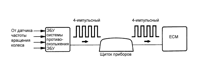
The wheel speed sensor monitors the wheel rotation speed and sends a signal to the skid control ECU. The skid control ECU converts the wheel speed signal into a 4-pulse signal and transmits it to the ECM via the combination meter. The ECM determines the vehicle speed based on the frequency of the pulse signal.
Tech Tips
-
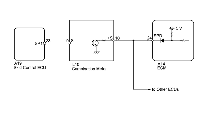
A voltage of 5 or 12 V is output from each ECU and then input to the combination meter. The signal is changed to a pulse signal at the transistor in the combination meter. Each ECU controls the respective system based on the pulse signal.
-
If a short occurs in any of the ECUs or in the wire harness connected to an ECU, all systems in the diagram below will not operate normally.
| DTC No. | DTC Detection Condition | Trouble Area |
|---|---|---|
| P0500 | While vehicle being driven, no vehicle speed sensor signal to ECM. (2 trip detection logic) |
|
WIRING DIAGRAM
INSPECTION PROCEDURE
Tech Tips
Read freeze frame data using the intelligent tester. The ECM records vehicle and driving condition information as freeze frame data the moment a DTC is stored. When troubleshooting, freeze frame data can help determine if the vehicle was moving or stationary, if the engine was warmed up or not, if the air-fuel ratio was lean or rich, and other data from the time the malfunction occurred.
PROCEDURE
-
CHECK OPERATION OF SPEEDOMETER
-
Drive the vehicle and check whether the operation of the speedometer in the combination meter is normal.
Tech Tips
-
The vehicle speed sensor is operating normally if the speedometer reading is normal.
-
If the speedometer does not operate, check it by following the procedure described in speedometer malfunction Click here.
-
NG 
GO TO MALFUNCTION IN SPEEDOMETER Click here
OK 
-
-
READ VALUE USING INTELLIGENT TESTER (VEHICLE SPEED)
-
Connect the intelligent tester to the DLC3.
-
Turn the engine switch on (IG) and turn the tester ON.
-
Enter the following menus: Powertrain / Engine / Data List / Vehicle Speed.
-
Drive the vehicle.
-
Read the value displayed on the tester.
OK Vehicle speeds displayed on tester and speedometer display are equal.
NG 
CHECK HARNESS AND CONNECTOR (COMBINATION METER - ECM) Click here
OK 
CHECK FOR INTERMITTENT PROBLEMS Click here
-
-
CHECK HARNESS AND CONNECTOR (COMBINATION METER - ECM)
-
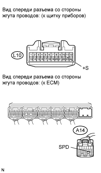
Disconnect the L10 combination meter connector.
-
Disconnect the A14 ECM connector.
-
Measure the resistance according to the value(s) in the table below.
Standard resistance (Check for open) Tester Connection Condition Specified Condition L10-10 (+S) - A14-24 (SPD) Always Below 1 Ω Standard resistance (Check for short) Tester Connection Condition Specified Condition L10-10 (+S) or A14-24 (SPD) - Body ground Always 10 kΩ or higher Tech Tips
If the wire has a short, check the speed signal circuit in other systems related to the vehicle speed signal (e.g. the navigation system, audio system, etc.).
NG
REPAIR OR REPLACE HARNESS OR CONNECTOR
OK
-
-
CHECK COMBINATION METER (+S VOLTAGE)
-
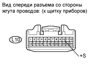
Disconnect the L10 combination meter connector.
-
Turn the engine switch on (IG).
-
Measure the voltage according to the value(s) in the table below.
Standard voltage Tester Connection Switch Condition Specified Condition L10-10 (+S) - Body ground Engine switch on (IG) 4.5 to 5.5 V Tech Tips
A voltage of 5 or 12 V is output from each ECU and then input to the combination meter.
NG
REPLACE ECM Click here
OK
-
-
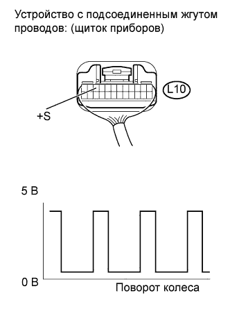
CHECK COMBINATION METER (SPD SIGNAL OUTPUT WAVEFORM)
-
Move the shift lever to N.
-
Jack up the vehicle.
-
Turn the engine switch on (IG).
-
Measure the voltage according to the value(s) in the table below.
Standard voltage Tester Connection Condition Specified Condition L10-10 (+S) - Body ground
-
Engine switch on (IG)
-
Wheel turned slowly
Voltage generated intermittently Tech Tips
-
The output voltage should fluctuate up and down, similarly to the diagram, when the wheel is turned slowly.
-
A voltage of 5 or 12 V is output from each ECU and then input to the combination meter.
-
NG
CHECK COMBINATION METER (SPD SIGNAL INPUT WAVEFORM) Click here
OK
REPLACE ECM Click here
-
-
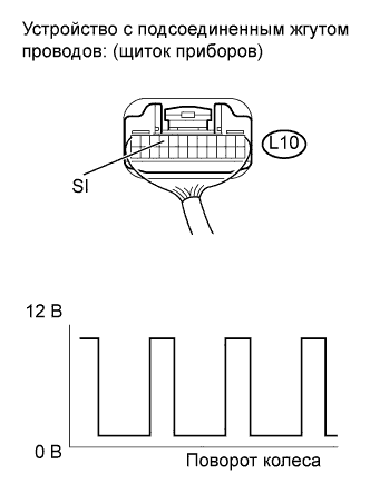
CHECK COMBINATION METER (SPD SIGNAL INPUT WAVEFORM)
-
Move the shift lever to N.
-
Jack up the vehicle.
-
Turn the engine switch on (IG).
-
Measure the voltage according to the value(s) in the table below.
Standard voltage Tester Connection Condition Specified Condition L10-9 (SI) - Body ground
-
Engine switch on (IG)
-
Wheel turned slowly
Voltage generated intermittently Tech Tips
The output voltage should fluctuate up and down, similarly to the diagram, when the wheel is turned slowly.
-
NG
CHECK HARNESS AND CONNECTOR (COMBINATION METER - SKID CONTROL ECU) Click here
OK
REPLACE NO. 1 METER ECU Click here
-
-
CHECK HARNESS AND CONNECTOR (COMBINATION METER - SKID CONTROL ECU)
-
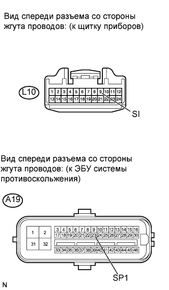
Disconnect the L10 combination meter connector.
-
Disconnect the A19 skid control ECU connector.
-
Measure the resistance according to the value(s) in the table below.
Standard resistance (Check for open) Tester Connection Condition Specified Condition L10-9 (SI) - A19-23 (SP1) Always Below 1 Ω Standard resistance (Check for short) Tester Connection Condition Specified Condition L10-9 (SI) or A19-23 (SP1) - Body ground Always 10 kΩ or higher
NG
REPAIR OR REPLACE HARNESS OR CONNECTOR
OK
REPLACE SKID CONTROL ECU Click here
-