| DTC Code | DTC Name |
|---|---|
| P0420 | Catalyst System Efficiency Below Threshold (Bank 1) |
| P0430 | Catalyst System Efficiency Below Threshold (Bank 2) |
MONITOR DESCRIPTION
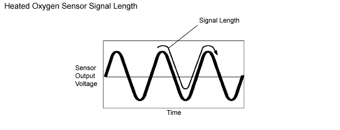
The ECM uses heated oxygen sensors mounted before and after the Three-Way Catalyst (TWC) to monitor its efficiency. The front sensor sends pre-catalyst air-fuel information to the ECM. The rear sensor sends post-catalyst information to the ECM. The ECM compares these 2 signals to judge the efficiency of the catalyst and the catalyst's ability to store oxygen. During normal operation, the TWC stores and releases oxygen as needed. The capacity to store oxygen results in a low variation in the post-TWC exhaust stream as shown below.
If the catalyst is functioning normally, the waveform of the heated oxygen sensor (sensor 2) slowly switches between RICH and LEAN. If the catalyst is deteriorated, the waveform will alternate frequently between RICH and LEAN.
As the catalyst efficiency degrades, its ability to store oxygen is reduced and the catalyst output becomes more variable.
When running the catalyst monitor, the ECM begins to measure the signal length of the heated oxygen sensor (sensor 1) and heated oxygen sensor (sensor 2). The ECM calculates the rate of the signal length of the heated oxygen sensor (sensor 1) and heated oxygen sensor (sensor 2) (catalyst deterioration level). If the catalyst deterioration level exceeds the threshold, the ECM interprets this as a catalyst malfunction. The ECM illuminates the MIL (2 trip detection logic) and sets a DTC.
The monitor runs after:
-
The engine is warmed up (Engine Coolant Temperature (ECT) is 75°C (167°F) or more).
-
The vehicle is driven at approximately 60 to 100 km/h (37 to 63 mph) for 15 minutes.
| DTC No. | DTC Detection Condition | Trouble Area |
|---|---|---|
| P0420 P0430 |
|
|
CONFIRMATION DRIVING PATTERN
-
Connect the intelligent tester to the DLC3.
-
Start the engine and warm it up with all the accessories switched OFF until the ECT becomes stable.
-
Run the engine at 1100 to 1600 rpm for about 3 minutes.
Tip:Control the engine RPM so that the calculated catalyst temperature can be between 450 and 850°C (810 and 1562°F). The calculated catalyst temperatures of bank 1 and bank 2 can be read by viewing Catalyst Temp B1S1 and Catalyst Temp B2S1 of the Data List.
-
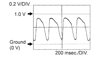
Confirm that heated oxygen sensor [bank 1 sensor 1 (OX1A) and bank 2 sensor 1 (OX2A)] have waveforms that are around 0.5 V during feedback to the ECM. Then check the waveform of the heated oxygen sensor [bank 1 sensor 2 (OX1B) and bank 2 sensor 2 (OX2B)] for the same waveforms (0.5 V during feedback).
Tip:If there is a malfunction in the catalyst, the waveform of the heated oxygen sensor (sensor 2) (OX1B, OX2B) is almost the same as that of the heated oxygen sensor (sensor 1) (OX1A, OX2A), which is shown.
INSPECTION PROCEDURE
-
If a malfunction cannot be found when troubleshooting DTC P0420 or P0430, a lean or rich abnormality may be the cause. Perform troubleshooting by following the inspection procedure for P0171 or P0174 (System Too Lean) and P0172 or P0175 (System Too Rich).
-
Read freeze frame data using the intelligent tester. Freeze frame data records the engine conditions when a malfunction is detected. When troubleshooting, freeze frame data can help determine if the vehicle was moving or stationary, if the engine was warmed up or not, if the air-fuel ratio was LEAN or RICH, and other data from the time the malfunction occurred.
-
If DTC P0420 is displayed, check the bank 1 catalyst.
-
If DTC P0430 is displayed, check the bank 2 catalyst.
-
Bank 1 includes cylinder No. 1, but bank 2 does not. Cylinder No. 1 is located in the front part of the engine, opposite the transmission.
PROCEDURE
- Click here
CHECK ANY OTHER DTCS OUTPUT (IN ADDITION TO DTC P0420, P0430)
-
Connect the intelligent tester to the DLC3.
-
Turn the engine switch on (IG) and turn the tester ON.
-
Enter the following menus: Powertrain / Engine / DTC.
-
Read the DTCs.
Result Display (DTC output) Proceed to P0420 or P0430 A P0420 or P0430 and other DTCs B
-
- Click here
PERFORM ACTIVE TEST USING INTELLIGENT TESTER (CONTROL THE INJECTION VOLUME FOR A/F SENSOR)
-
Connect the intelligent tester to the DLC3.
-
Turn the engine switch on (IG) and turn the tester ON.
-
Start the engine.
-
Warm up the engine at an engine speed of 2500 rpm for approximately 90 seconds.
-
Enter the following menus: Powertrain / Engine / Active Test / Control the Injection Volume for A/F Sensor.
-
Perform the "Control the Injection Volume for A/F Sensor" operation with the engine idling (press the RIGHT or LEFT button to change the fuel injection volume).
-
Monitor the voltage outputs of the HO2 sensor (O2S B1S1, O2S B2S1, O2S B1S2 and O2S B2S2) displayed on the tester.
Tip:
-
The "Control the Injection Volume for A/F sensor" operation lowers the fuel injection volume by 12.5% or increases the injection volume by 12.5%.
-
Each sensor reacts in accordance with increases and decreases in the fuel injection volume.
Standard Tester Display (Sensor) Injection Volume Status Voltage O2S B1S1 or O2S B2S1
(Front HO2 Sensor)
+12.5% Rich More than 0.55 O2S B1S1 or O2S B2S1
(Front HO2 Sensor)
-12.5% Lean Less than 0.4 O2S B1S2 or O2S B2S2
(Rear HO2 Sensor)
+12.5% Rich More than 0.5 O2S B1S2 or O2S B2S2
(Rear HO2 Sensor)
-12.5% Lean Less than 0.4 Result Status
O2S B1S1 or O2S B2S1
Status
O2S B1S2 or O2S B2S2
A/F Condition and HO2 Sensors (sensors 1 and 2) Condition Misfire Main Suspected Trouble Area Proceed to Lean / Rich Lean / Rich Normal -
-
TWC
-
Gas leakage from exhaust system
A Lean Lean / Rich HO2 sensor (sensor 1) malfunction - HO2 sensor (sensor 1) B Rich Lean / Rich HO2 sensor (sensor 1) malfunction - HO2 sensor (sensor 1) B Lean / Rich Lean HO2 sensor (sensor 2) malfunction -
-
HO2 sensor (sensor 2)
-
Gas leakage from exhaust system
C Lean / Rich Rich HO2 sensor (sensor 2) malfunction -
-
HO2 sensor (sensor 2)
-
Gas leakage from exhaust system
C Lean Lean Actual air-fuel ratio (A/F) lean May occur
-
Extremely rich or lean actual A/F
-
Gas leakage from exhaust system
A Rich Rich Actual A/F rich -
-
Extremely rich or lean actual A/F
-
Gas leakage from exhaust system
A Lean: During "Control the Injection Volume for A/F sensor", the HO2 sensor output voltages are consistently less than 0.4 V.
Rich: During "Control the Injection Volume for A/F sensor", the HO2 sensor S1 (S2) output voltages are consistently more than 0.55 V (0.5 V).
-
-
- Click here
CHECK FOR EXHAUST GAS LEAKAGE
OK No gas leakage.
- OKClick here
- NGClick here
- Click here
CHECK DTC OUTPUT (DTC P0420 AND/OR P0430)
-
According to the output DTCs in the step 1 (Check Any Other DTCs Output), proceed to next step referring to the table below.
Result Display (DTC output) Proceed to P0420 A P0430 B P0420 and P0430 A and B
-
- Click here
REPLACE EXHAUST MANIFOLD SUB-ASSEMBLY LH (TWC: FRONT CATALYST)
-
Replace the exhaust manifold sub-assembly LH (Click here).
- NEXTClick here
-
- Click here
GO TO DTC CHARTClick here
- Click here
CHECK AND REPLACE HEATED OXYGEN SENSOR (SENSOR 1)Click here
- Click here
CHECK AND REPLACE HEATED OXYGEN SENSOR (SENSOR 2), OR CHECK AND REPAIR EXHAUST GAS LEAKAGEClick here
- Click here
REPAIR OR REPLACE EXHAUST GAS LEAKAGE POINT
- Click here
REPLACE EXHAUST MANIFOLD SUB-ASSEMBLY RH (TWC: FRONT CATALYST)
-
Replace the exhaust manifold sub-assembly RH (Click here).
- NEXTClick here
-
- Click here
REPLACE FRONT EXHAUST PIPE ASSEMBLY (TWC: REAR CATALYST)Click here