СИСТЕМА SFI РЕЖИМЫ DATA LIST / ACTIVE TEST
-
DATA LIST
Tech Tips
Using the GTS to read the Data List allows the values or states of switches, sensors, actuators and other items to be read without removing any parts. This non-intrusive inspection can be very useful because intermittent conditions or signals may be discovered before parts or wiring is disturbed. Reading the Data List information early in troubleshooting is one way to save diagnostic time.
Note
In the table below, the values listed under "Normal Condition" are reference values. Do not depend solely on these reference values when deciding whether a part is faulty or not.
-
Warm up the engine.
-
Turn the engine switch off.
-
Connect the GTS to the DLC3.
-
Turn the engine switch on (IG).
-
Turn the GTS on.
-
Enter the following menus: Powertrain / Engine / Data List /
-
Check the values by referring to the table below.
Tester Display Measurement Item/Range Normal Condition Diagnostic Note Vehicle Speed Vehicle speed:
Min.: 0 km/h, Max.: 255 km/h
Actual vehicle speed Speed indicated on speedometer Engine Speed Engine speed:
Min.: 0 rpm, Max.: 16383 rpm
700 to 800 rpm: Idling - Calculate Load Load calculated by ECM:
Min.: 0%, Max.: 100%
-
15 to 35%: Idling
-
15 to 35%: Running without load (2000 rpm)
- Vehicle Load Vehicle load:
Min.: 0%, Max.: 25700%
Actual vehicle load - MAF Sensor 1 Supported Status of the MAF sensor 1 supported:
Supp or Unsupp
Supp - MAF Sensor 1 Air flow rate from mass air flow meter (bank 1):
Min.: 0 g/s, Max.: 655.35 g/s
-
0.8 to 4.8 g/s: Idling
-
2.4 to 12.8 g/s: 2000 rpm
-
3.6 to 17.6 g/s: 3000 rpm
If value approximately 0.0 g/s:
-
Mass air flow meter power source circuit open
-
VG circuit open or shorted
If value 160.0 g/s or more:
-
E2G circuit open
MAF Sensor 2 Supported Status of the MAF sensor 2 supported:
Supp or Unsupp
Supp - MAF Sensor 2 Air flow rate from mass air flow meter (bank 2):
Min.: 0 g/s, Max.: 655.35 g/s
-
0.8 to 4.8 g/s: Idling
-
2.4 to 12.8 g/s: 2000 rpm
-
3.6 to 17.6 g/s: 3000 rpm
If value approximately 0.0 g/s:
-
Mass air flow meter power source circuit open
-
VG circuit open or shorted
If value 160.0 g/s or more:
-
E2G circuit open
Atmosphere Pressure Atmospheric pressure:
Min.: 0 kPa, Max.: 255 kPa
Equivalent to atmospheric pressure (absolute pressure) - Coolant Temp Engine coolant temperature:
Min.: -40°C, Max.: 215°C
80 to 105°C (176 to 221°F): After warming up
-
If value -40°C (-40°F): sensor circuit open
-
If value 140°C (284°F): sensor circuit shorted
Intake Air Temp B1S1 Supported Status of the intake air temp B1S1 supported:
Supp or Unsupp
Supp - Intake Air Temp B1S1 Intake air temperature (bank 1 sensor 1):
Min.: -40°C, Max.: 215°C
Equivalent to ambient air temperature
-
If value -40°C (-40°F): sensor circuit open
-
If value 140°C (284°F): sensor circuit shorted
Intake Air Temp B1S2 Supported Status of the intake air temp B1S2 supported:
Supp or Unsupp
Unsupp If this item displays "Unsupp", a fixed value is displayed for "Intake Air Temp B1S2", as intake air temperature sensors (bank 1 sensor 2) are not equipped on the vehicle. Intake Air Temp B1S2 Intake air temperature (bank 1 sensor 2):
Min.: -40°C, Max.: 215°C
- - Intake Air Temp B1S3 Supported Status of the intake air temp B1S3 supported:
Supp or Unsupp
Unsupp If this item displays "Unsupp", a fixed value is displayed for "Intake Air Temp B1S3", as intake air temperature sensors (bank 1 sensor 3) are not equipped on the vehicle. Intake Air Temp B1S3 Intake air temperature (bank 1 sensor 3):
Min.: -40°C, Max.: 215°C
- - Intake Air Temp B2S1 Supported Status of the intake air temp B2S1 supported:
Supp or Unsupp
Supp - Intake Air Temp B2S1 Intake air temperature (bank 2 sensor 1):
Min.: -40°C, Max.: 215°C
Equivalent to ambient air temperature
-
If value -40°C (-40°F): sensor circuit open
-
If value 140°C (284°F): sensor circuit shorted
Intake Air Temp B2S2 Supported Status of the Intake Air Temp B2S2 Supported:
Supp or Unsupp
Unsupp If this item displays "Unsupp", a fixed value is displayed for "Intake Air Temp B2S2", as intake air temperature sensors (bank 2 sensor 2) are not equipped on the vehicle. Intake Air Temp B2S2 Intake air temperature (bank 2 sensor 2):
Min.: -40°C, Max.: 215°C
- - Intake Air Temp B2S3 Supported Status of the intake air temp B2S3 supported Unsupp If this item displays "Unsupp", a fixed value is displayed for "Intake Air Temp", as intake air temperature sensors (bank 2 sensor 3) are not equipped on the vehicle. Intake Air Temp B2S3 Intake air temperature (bank 2 sensor 3):
Min.: -40°C, Max.: 215°C
- - Engine Run Time Engine run time:
Min.: 0 s, Max.: 65535 s
Time after engine start - Initial Engine Coolant Temp Initial engine coolant temperature:
Min.: -40°C, Max.: 119.3°C
Coolant temperature when engine started Service data Initial Intake Air Temp Initial intake air temperature:
Min.: -40°C, Max.: 119.3°C
Intake air temperature when engine started Service data Battery Voltage Battery voltage:
Min.: 0 V, Max.: 65.535 V
11 to 14 V: Idling - Accelerator Position Accelerator pedal position:
Min.: 0%, Max.: 399.9%
Actual accelerator pedal position - Accel Sens. No. 1 Volt % Absolute accelerator pedal position No. 1:
Min.: 0%, Max.: 100%
10 to 22%: accelerator pedal released
52 to 90%: accelerator pedal fully depressed
- Accel Sens. No. 2 Volt % Absolute accelerator pedal position No. 2:
Min.: 0%, Max.: 100%
24 to 40%: accelerator pedal released
68 to 95%: accelerator pedal fully depressed
- Accel Sensor Out No. 1 Accelerator pedal position sensor No. 1 voltage:
Min.: 0 V, Max.: 4.98 V
0.5 to 1.1 V: accelerator pedal released
2.6 to 4.5 V: accelerator pedal fully depressed
- Accel Sensor Out No. 2 Accelerator pedal position sensor No. 2 voltage:
Min.: 0 V, Max.: 4.98 V
1.2 to 2.0 V: accelerator pedal released
3.4 to 4.75 V: accelerator pedal fully depressed
- Accelerator Idle Position Whether or not accelerator pedal position sensor detecting idle:
ON or OFF
ON: Idling - Accel Fully Close Learn #1 Accelerator fully closed learned value No. 1:
Min.: 0 deg, Max.: 124.5 deg
- Electronic throttle control system service data Accel Fully Close Learn #2 Accelerator fully closed learned value No. 2:
Min.: 0 deg, Max.: 124.5 deg
- Electronic throttle control system service data Throttle Sensor Volt % Throttle sensor position:
Min.: 0%, Max.: 100%
10 to 22%: Idling Value calculated based on VTA Throttl Sensor #2 Volt % Throttle sensor position #2:
Min.: 0%, Max.: 100%
- Value calculated based on VTA2 ST1 Brake pedal signal:
ON or OFF
ON: Brake pedal depressed - System Guard System guard:
ON or OFF
- Electronic throttle control system service data Open Side Malfunction Open side malfunction:
ON or OFF
- Electronic throttle control system service data Throttle Idle Position Whether or not throttle position sensor detecting idle:
ON or OFF
ON: Idling - Throttle Require Position Required throttle position:
Min.: 0 V, Max.: 4.98 V
0.5 to 1.0 V: Idling - Throttle Sensor Position Throttle sensor position:
Min.: 0%, Max.: 100%
-
0 to 10%: Accelerator pedal released
-
64 to 96%: Accelerator pedal fully depressed
Recognition value for throttle opening angle in ECM Throttle Position No. 1 Throttle position No. 1:
Min.: 0 V, Max.: 4.98 V
-
0.5 to 1.1 V: Accelerator pedal released
-
3.2 to 4.8 V: Accelerator pedal fully depressed
- Throttle Position No. 2 Throttle position No. 2:
Min.: 0 V, Max.: 4.98 V
-
2.1 to 3.1 V: Accelerator pedal released
-
3.2 to 4.8 V: Accelerator pedal fully depressed
- Throttle Position Command Throttle position command value:
Min.: 0 V, Max.: 4.98 V
0.5 to 4.8 V Electronic throttle control system service data Throttle Sens Open Pos #1 Throttle sensor opener position No. 1:
Min.: 0 V, Max.: 4.98 V
0.6 to 0.9 V Electronic throttle control system service data Throttle Sens Open Pos #2 Throttle sensor opener position No. 2:
Min.: 0 V, Max.: 4.98 V
2.2 to 2.6 V Electronic throttle control system service data Throttle Motor Current Throttle actuator current:
Min.: 0 A, Max.: 19.9 A
0 to 3.0 A: Idling - Throttle Motor DUTY Throttle actuator:
Min.: 0%, Max.: 100%
10 to 20%: Idling - Throttle Motor Duty (Open) Throttle actuator opening duty ratio:
Min.: 0%, Max.: 255%
0 to 40%: During idling Electronic throttle control system service data Throttle Motor Duty (Close) Throttle actuator closed duty ratio:
Min.: 0%, Max.: 255%
0 to 40%: During idling Electronic throttle control system service data Throttle Fully Close Learn Throttle valve fully closed
(learned value):
Min.: 0 V, Max.: 4.98 V
0.4 to 0.8 V - +BM Voltage +BM voltage:
Min.: 0 V, Max.: 79.998 V
11 to 14 V: Idling Electronic throttle control system service data Actuator Power Supply Actuator power supply:
ON or OFF
ON: Idling Electronic throttle control system service data Injector (port) Injection period of No. 1 cylinder:
Min.: 0 μs, Max.: 65535 μs
0 to 2000 μs: Idling - Injector Volum (Cylinder 1) Injection volume (Cylinder 1):
Min.: 0 ml, Max.: 2.047 ml
0.05 to 0.15 ml: Idling Fuel injection volume for 10 injections Fuel Pump Speed Control Fuel pump speed control status:
ON or OFF
Idling: ON Active Test Fuel Pump / Speed Status Fuel pump status:
ON or OFF
ON: Cranking Active Test support data Current Fuel Type Status of the current fuel type Gasoline/petrol - EVAP (Purge) VSV VSV for EVAP control duty:
Min.: 0%, Max.: 100%
10 to 50%: During Idling Active Test support data Evap Purge Flow Purge flow:
Min.: 0%, Max.: 399.9%
0 to 4%: Idling Service data Purge Density Learn Value Purge density learned value:
Min.: -200, Max.: 199.993
-35 to 1: Idling Service data EVAP Purge VSV VSV status for EVAP control:
ON or OFF
- - Purge Cut VSV Duty Purge cut VSV duty:
Min.: 0%, Max.: 399.9%
- - Target Air-Fuel Ratio Air-fuel ratio:
Min.: 0, Max.: 1.99
0.8 to 1.2: During idling - O2S B1S1 Heated oxygen sensor output voltage for bank 1 sensor 1:
Min.: 0 V, Max.: 1.275 V
0.1 to 0.9 V - O2S B1S2 Heated oxygen sensor output voltage for bank 1 sensor 2:
Min.: 0 V, Max.: 1.275 V
0.1 to 0.9 V: Driving at 70 km/h (44 mph) Performing Control the Injection Volume or Control the Injection Volume for A/F Sensor function of Active Test enables technician to check output voltage of sensor O2S B2S1 Heated oxygen sensor output voltage for bank 2 sensor 1:
Min.: 0 V, Max.: 1.275 V
0.1 to 0.9 V - O2S B2S2 Heated oxygen sensor output voltage for bank 2 sensor 2:
Min.: 0 V, Max.: 1.275 V
0.1 to 0.9 V: Driving at 70 km/h (44 mph) Performing Control the Injection Volume or Control the Injection Volume for A/F Sensor function of Active Test enables technician to check output voltage of sensor O2 LR Switch Time B1S1 Heated oxygen sensor (bank 1 sensor 1) voltage LEAN to RICH switching time:
Min.: 0 ms, Max.: 16711.68 ms
Within 1000 ms - O2 LR Switch Time B2S1 Heated oxygen sensor (bank 2 sensor 1) voltage LEAN to RICH switching time:
Min.: 0 ms, Max.: 16711.68 ms
Within 1000 ms - O2 RL Switch Time B1S1 Heated oxygen sensor (bank 1 sensor 1) voltage RICH to LEAN switching time:
Min.: 0 ms, Max.: 16711.68 ms
Within 1000 ms - O2 RL Switch Time B2S1 Heated oxygen sensor (bank 2 sensor 1) voltage RICH to LEAN switching time:
Min.: 0 ms, Max.: 16711.68 ms
Within 1000 ms - O2S Impedance B1S2 Heated oxygen sensor (bank 1 sensor 2) impedance:
Min.: 0 ohm, Max.: 21247.67 ohm
5 to 15000 ohm After driving approximately 10 minutes in urban area O2S Impedance B2S2 Heated oxygen sensor (bank 2 sensor 2) impedance:
Min.: 0 ohm, Max.: 21247.67 ohm
5 to 15000 ohm After driving approximately 10 minutes in urban area O2 Heater B1S1 Heated oxygen sensor heater for bank 1 sensor 1:
ON or OFF
- - O2 Heater B1S2 Heated oxygen sensor heater for bank 1 sensor 2:
Active or Not Act
- - O2 Heater B2S1 Heated oxygen sensor heater for bank 2 sensor 1:
ON or OFF
- - O2 Heater B2S2 Heated oxygen sensor heater for bank 2 sensor 2:
Active or Not Act
- - O2 Heater Curr Val B1S1 Heated oxygen sensor current for bank 1 sensor 1:
Min.: 0 A, Max.: 4.9 A
- - O2 Heater Curr Val B2S1 Heated oxygen sensor current for bank 2 sensor 1:
Min.: 0 A, Max.: 4.9 A
- - O2 Heater Curr Val B1S2 Heated oxygen sensor current for bank 1 sensor 2:
Min.: 0 A, Max.: 4.9 A
- - O2 Heater Curr Val B2S2 Heated oxygen sensor current for bank 2 sensor 2:
Min.: 0 A, Max.: 4.9 A
- - Short FT #1 Short-term fuel trim of bank 1:
Min.: -100%, Max.: 99.2%
-20 to 20% Short-term fuel compensation used to maintain air fuel ratio at stoichiometric air fuel ratio Long FT #1 Long-term fuel trim of bank 1:
Min.: -100%, Max.: 99.2%
-30 to 30%
-
Overall fuel compensation carried out in long term to compensate for continual deviation of short-term fuel trim from central value
-
Air fuel ratio feedback leaning is divided up according to the engine operating range (engine speed x load), and separate values are stored for each operating range. "Long FT #1" indicates the learned value for the current operating range. [A/F Learn Value Idle #1], [A/F Learn Value Low #1], [A/F Learn Value Mid1 #1], [A/ F Learn Value Mid2 #1] and [A/ F Learn Value High #1] indicate the leaned values for the different operating ranges. The learned value that is the same as "Long FT #1" indicates the current engine operating range.
A/F Learn Value Idle #1 Air fuel ratio learn value area of idle (for Bank 1):
Min.: -50%, Max.: 49.6%
- Learning is performed when idling with the engine warmed up (engine coolant temperature is 80°C [176°F] or higher). A/F Learn Value Low #1 Air fuel ratio learn value area of low load (for Bank 1):
Min.: -50%, Max.: 49.6%
- Learning is performed when driving with the engine warmed up (engine coolant temperature is 80°C [176°F] or higher) and operating in the low load range (when the range of engine loads is divided into four parts). A/F Learn Value Mid1 #1 Air fuel ratio learn value area of middle load 1 (for Bank 1):
Min.: -50%, Max.: 49.6%
- Learning is performed when driving with the engine warmed up (engine coolant temperature is 80°C [176°F] or higher) and operating in the midsize load range closer to the low load range (when the range of engine loads is divided into four parts). A/F Learn Value Mid2 #1 Air fuel ratio learn value area of middle load 2 (for Bank 1):
Min.: -50%, Max.: 49.6%
- Learning is performed when driving with the engine warmed up (engine coolant temperature is 80°C [176°F] or higher) and operating in the midsize load range closer to the high load range (when the range of engine loads is divided into four parts). A/F Learn Value High #1 Air fuel ratio learn value area of high load (for Bank 1):
Min.: -50%, Max.: 49.6%
- Learning is performed when driving with the engine warmed up (engine coolant temperature is 80°C [176°F] or higher) and operating in the high load range (when the range of engine loads is divided into four parts). Total FT #1 Total fuel trim of bank 1:
Min.: -0.5, Max.: 0.496
-0.28 to 0.2: Idling - Short FT #2 Short-term fuel trim of bank 2:
Min.: -100%, Max.: 99.2%
-20 to 20% Short-term fuel compensation used to maintain air fuel ratio at stoichiometric air fuel ratio Long FT #2 Long-term fuel trim of bank 2:
Min.: -100%, Max.: 99.2%
-30 to 30%
-
Overall fuel compensation carried out in long term to compensate for continual deviation of short-term fuel trim from central value
-
Air fuel ratio feedback leaning is divided up according to the engine operating range (engine speed x load), and separate values are stored for each operating range. "Long FT #2" indicates the learned value for the current operating range. [A/F Learn Value Idle #2], [A/F Learn Value Low #2], [A/F Learn Value Mid1 #2], [A/ F Learn Value Mid2 #2] and [A/ F Learn Value High #2] indicate the leaned values for the different operating ranges. The learned value that is the same as "Long FT #2" indicates the current engine operating range.
A/F Learn Value Idle #2 Air fuel ratio learn value area of idle (for Bank 2):
Min.: -50%, Max.: 49.6%
- Learning is performed when idling with the engine warmed up (engine coolant temperature is 80°C [176°F] or higher). A/F Learn Value Low #2 Air fuel ratio learn value area of low load (for Bank 2):
Min.: -50%, Max.: 49.6%
- Learning is performed when driving with the engine warmed up (engine coolant temperature is 80°C [176°F] or higher) and operating in the low load range (when the range of engine loads is divided into four parts). A/F Learn Value Mid1 #2 Air fuel ratio learn value area of middle load 1 (for Bank 2):
Min.: -50%, Max.: 49.6%
- Learning is performed when driving with the engine warmed up (engine coolant temperature is 80°C [176°F] or higher) and operating in the midsize load range closer to the low load range (when the range of engine loads is divided into four parts). A/F Learn Value Mid2 #2 Air fuel ratio learn value area of middle load 2 (for Bank 2):
Min.: -50%, Max.: 49.6%
- Learning is performed when driving with the engine warmed up (engine coolant temperature is 80°C [176°F] or higher) and operating in the midsize load range closer to the high load range (when the range of engine loads is divided into four parts). A/F Learn Value High #2 Air fuel ratio learn value area of high load (for Bank 2):
Min.: -50%, Max.: 49.6%
- Learning is performed when driving with the engine warmed up (engine coolant temperature is 80°C [176°F] or higher) and operating in the high load range (when the range of engine loads is divided into four parts). Total FT #2 Total fuel trim of bank 2:
Min.: -0.5, Max.: 0.496
-0.28 to 0.2: Idling - Fuel System Status #1 Fuel system status (bank 1):
OL, CL, OLDrive, OLFault or CLFault
CL: Idling after warming up
-
OL (Open Loop): Has not yet satisfied conditions to go to closed loop
-
CL (Closed Loop): Using heated oxygen sensor (sensor 1) as feedback for fuel control
-
OLDrive: Open loop due to driving conditions (fuel enrichment)
-
OLFault: Open loop due to detected system fault
-
CLFault: Closed loop but heated oxygen sensor (sensor 1), which used for fuel control, malfunctioning
Fuel System Status #2 Fuel system status (bank 2):
OL, CL, OLDrive, OLFault or CLFault
CL: Idling after warming up
-
OL (Open Loop): Has not yet satisfied conditions to go to closed loop
-
CL (Closed Loop): Using heated oxygen sensor (sensor 1) as feedback for fuel control
-
OLDrive: Open loop due to driving conditions (fuel enrichment)
-
OLFault: Open loop due to detected system fault
-
CLFault: Closed loop but heated oxygen sensor (sensor 1), which used for fuel control, malfunctioning
O2FT B1S1 Short-term fuel trim (bank 1):
-100 to 99.2%
0 +-20% - O2FT B2S1 Short-term fuel trim (bank 2):
-100 to 99.2%
0 +-20% - IGN Advance Ignition timing advance for No. 1 cylinder:
Min.: -64 deg., Max.: 63.5 deg
BTDC 5 to 22 deg: Idling - Knock Feedback Value Knocking feedback value:
Min: -1024°CA, Max.: 1023.9°CA
-31.5 to 0°CA: Driving at 70 km/h (44 mph) Service data Knock Correct Learn Value Knocking correction learned value:
Min: -1024°CA, Max.: 1023.9°CA
3 to 31.5°CA: Driving at 70 km/h (44 mph) Service data ACIS Motor Duty ACIS motor duty:
Min.: -200%, Max.: 199.99%
- Active Test support data VVT Change Angle #1* VVT intake side displacement angle (bank 1):
Min.: 0 DegFR, Max.: 639.9 DegFR
0 DegFR: Idling Displacement angle during forced operation VVT Change Angle #2* VVT intake side displacement angle (bank 2):
Min.: 0 DegFR, Max.: 639.9 DegFR
0 DegFR: Idling Displacement angle during forced operation VVT Ex Hold Lrn Val #1* VVT exhaust hold duty ratio learned value (bank 1):
Min.: 0%, Max.: 399.9%
0 to 80%: Idling - VVT Ex Chg Angle #1* VVT exhaust displacement angle (bank 1):
Min.: 0 DegFR, Max.: 639.9 DegFR
0 to 40 DegFR: Idling - VVT Ex OCV Duty #1* VVT exhaust camshaft timing oil control valve duty (bank 1):
Min.: 0%, Max.: 399.9%
0 to 100%: Idling - VVT Ex Hold Lrn Val #2* VVT exhaust hold duty ratio learned value (bank 2):
Min.: 0%, Max.: 399.9%
0 to 80%: Idling - VVT Ex Chg Angle #2* VVT exhaust displacement angle (bank 2):
Min.: 0 DegFR, Max.: 639.9 DegFR
0 to 40 DegFR: Idling - VVT Ex OCV Duty #2* VVT exhaust camshaft timing oil control valve duty (bank 2):
Min.: 0%, Max.: 399.9%
0 to 100%: Idling - VVT-iE Aim Angle #1 VVT drive motor target angle bank 1:
Min.: 0 DegFR, Max.: 639.9 DegFR
10 DegFR: Idling - VVT-iE Aim Angle #2 VVT drive motor target angle bank 2:
Min.: 0 DegFR, Max.: 639.9 DegFR
10 DegFR: Idling - VVT-iE Mot Direction #1 VVT drive motor direction bank 1:
Backward or Forward
Forward: Idling - VVT-iE Mot Direction #2 VVT drive motor direction bank 2:
Backward or Forward
Forward: Idling - VN Turbo Type Variable nozzle turbo type:
Not Avl, Commo, Vacuum or CAN Com
Not Avl (Unused) - Catalyst Temp B1S1 Catalyst temperature (bank 1, sensor 1):
Min.: -40°C, Max.: 6513.5°C
- - Catalyst Temp B2S1 Catalyst temperature (bank 2, sensor 1):
Min.: -40°C, Max.: 6513.5°C
- - Catalyst Temp B1S2 Catalyst temperature (bank 1, sensor 2):
Min.: -40°C, Max.: 6513.5°C
- - Catalyst Temp B2S2 Catalyst temperature (bank 2, sensor 2):
Min.: -40°C, Max.: 6513.5°C
- - Starter Signal Starter signal:
Open or Close
Open: Cranking - Starter Control Starter switch status:
ON or OFF
ON: Cranking - Starter Relay Starter relay:
ON or OFF
ON: Cranking - ACC Relay ACC relay:
ON or OFF
ON: Cranking - Neutral Position SW Signal Park/neutral position switch assembly status:
ON or OFF
ON: P or N position - Stop Light Switch Stop light switch:
ON or OFF
ON: Brake pedal depressed - A/C Signal A/C signal:
ON or OFF
ON: A/C ON - Idle Up Signal Idle up signal:
ON or OFF
- - Closed Throttle Position SW Closed throttle position switch:
ON or OFF
-
ON: Throttle fully closed
-
OFF: Throttle open
- Fuel Cut Condition Fuel cut condition:
ON or OFF
ON: Fuel cut operating - Immobiliser Communication Immobiliser communication:
ON or OFF
ON: Normal - Check Mode Check mode:
ON or OFF
ON: Check mode ON SPD Test Result Check mode result for speed signal:
Compl or Incmpl
- - Misfire Test Result Check mode result for misfire monitor:
Compl or Incmpl
- - OXS1 Test Result Check mode result for HO2 sensor (bank 1):
Compl or Incmpl
- - OXS2 Test Result Check mode result for HO2 sensor (bank 2):
Compl or Incmpl
- - Complete Parts Monitor Comprehensive component monitor:
Not Avl or Avail
- Comprehensive Component Monitor Fuel System Monitor Fuel system monitor:
Not Avl or Avail
- Fuel System Monitor Misfire Monitor Misfire monitor:
Not Avl or Avail
- Misfire Monitor EGR/VVT Monitor EGR/VVT monitor:
Not Avl or Avail
- - EGR/VVT Monitor EGR/VVT monitor:
Compl or Incmpl
- - O2S (A/FS) Heater Monitor O2S (A/FS) heater monitor:
Not Avl or Avail
- - O2S (A/FS) Heater Monitor O2S (A/FS) heater monitor:
Compl or Incmpl
- - O2S (A/FS) Monitor O2S (A/FS) monitor:
Not Avl or Avail
- - O2S (A/FS) Monitor O2S (A/FS) monitor:
Compl or Incmpl
- - A/C Monitor A/C monitor:
Not Avl or Avail
- - A/C Monitor A/C monitor:
Compl or Incmpl
- - 2nd Air Monitor 2nd air monitor:
Not Avl or Avail
- - 2nd Air Monitor 2nd air monitor:
Compl or Incmpl
- - EVAP Monitor EVAP monitor:
Not Avl or Avail
- - EVAP Monitor EVAP monitor:
Compl or Incmpl
- - Heated Catalyst Monitor Heated catalyst monitor:
Not Avl or Avail
- - Heated Catalyst Monitor Heated catalyst monitor:
Compl or Incmpl
- - Catalyst Monitor Catalyst monitor:
Not Avl or Avail
- - Catalyst Monitor Catalyst monitor:
Compl or Incmpl
- - TC Terminal TC terminal status:
ON or OFF
- - # Codes (Include History) Number of emissions-related DTCs:
Min.: 0, Max.: 255
- Number of detected DTCs MIL MIL status:
ON or OFF
ON: MIL ON - MIL ON Run Distance MIL ON run distance:
Min.: 0 km, Max.: 65535 km
Distance driven after DTC detected - Running Time from MIL ON Running time from MIL ON:
Min.: 0 min, Max.: 65535 min
Equivalent to running time after MIL turned ON - Time After DTC Cleared Time after DTC cleared:
Min.: 0 min, Max.: 65535 min
Equivalent to time elapsed after DTCs erased - Distance from DTC Cleared Distance driven after DTCs cleared:
Min.: 0 km, Max.: 65535 km
Equivalent to distance driven after DTCs erased - Warmup Cycle Cleared DTC Warmup cycles after DTCs cleared:
Min.: 0, Max.: 255
- Number of warmup cycles after DTCs cleared Dist Batt Cable Disconnect Distance driven after battery cable disconnected:
Min.: 0 km, Max.: 65535 km
- - OBD Requirements OBD requirement EOBD (Euro OBD)
or
Brazil OBD Phase 2
- Number of Emission DTC Number of emissions-related DTCs - - TC and TE1 TC and TE1 terminals of DLC3:
ON or OFF
- Active Test support data Ignition Trig. Count Misfire count:
Min.: 0, Max.: 65535
0 to 800 - Cylinder #1 Misfire Count Misfire count of cylinder 1:
Min.: 0, Max.: 255
0 - Cylinder #2 Misfire Count Misfire count of cylinder 2:
Min.: 0, Max.: 255
0 - Cylinder #3 Misfire Count Misfire count of cylinder 3:
Min.: 0, Max.: 255
0 - Cylinder #4 Misfire Count Misfire count of cylinder 4:
Min.: 0, Max.: 255
0 - Cylinder #5 Misfire Count Misfire count of cylinder 5:
Min.: 0, Max.: 255
0 - Cylinder #6 Misfire Count Misfire count of cylinder 6:
Min.: 0, Max.: 255
0 - Cylinder #7 Misfire Count Misfire count of cylinder 7:
Min.: 0, Max.: 255
0 - Cylinder #8 Misfire Count Misfire count of cylinder 8:
Min.: 0, Max.: 255
0 - All Cylinders Misfire Count Misfire count of all cylinders:
Min.: 0, Max.: 255
0 to 35 - Multi Cylinders Misfire Count Misfire count of multiple cylinders:
Min.: 0, Max.: 65535
0 to 65535 - Misfire RPM Average engine speed during misfire:
Min.: 0 rpm, Max.: 6375 rpm
0 rpm: 0 Misfires - Misfire Load Average load during misfire:
Min.: 0 g/rev, Max.: 3.98 g/rev
0 g/rev: 0 Misfires - Misfire Margin Misfire margin:
Min.: -128%, Max.: 127%
0 to 127% Misfire detecting margin Electric Fan Motor Electric fan motor:
ON or OFF
ON: Electric fan motor operating Active Test support data Brake Override System Brake override system status
ON or OFF
ON: Brake override system operation - Idle Fuel Cut Prohibit Idle fuel cut:
ON or OFF
ON: Fuel cut operating Idle fuel cut is "ON" when throttle valve fully closed and engine speed over 2800 rpm Idle Fuel Cut Idle fuel cut:
ON or OFF
ON: Fuel cut operating Idle fuel cut is "ON" when throttle valve fully closed and engine speed over 2800 rpm FC TAU Fuel cut TAU (Fuel cut during very light load):
ON or OFF
ON: Fuel cut operating Fuel cut being performed under very light load to prevent engine combustion from becoming incomplete Communication with ECT Status of communication with ECT:
Comm or No Comm
- - Electrical Load Signal 1 Electrical load signal:
ON or OFF
- - Model Code Model code - Identifies model code:
USF4#
Engine Type Engine type - Identifies engine type:
1URFE
Cylinder Number Number of cylinders:
Min.: 0, Max.: 255
- Identifies number of cylinders:
8
Transmission Type Transmission type - Identifies transmission type:
ECT (8th)
Destination Destination - Identifies destination:
W
Model Year Model year:
Min.: 1900, Max.: 2155
- Identifies model year:
20##
System Identification System identification - Identifies engine system:
Gasoline (gasoline engine)
Engine Speed of Cyl #1 Engine rpm during No. 1 cylinder fuel cut:
Min.: 0 rpm, Max.: 51199 rpm
- Active Test support data Engine Speed of Cyl #2 Engine rpm during No. 2 cylinder fuel cut:
Min.: 0 rpm, Max.: 51199 rpm
- Active Test support data Engine Speed of Cyl #3 Engine rpm during No. 3 cylinder fuel cut:
Min.: 0 rpm, Max.: 51199 rpm
- Active Test support data Engine Speed of Cyl #4 Engine rpm during No. 4 cylinder fuel cut:
Min.: 0 rpm, Max.: 51199 rpm
- Active Test support data Engine Speed of Cyl #5 Engine rpm during No. 5 cylinder fuel cut:
Min.: 0 rpm, Max.: 51199 rpm
- Active Test support data Engine Speed of Cyl #6 Engine rpm during No. 6 cylinder fuel cut:
Min.: 0 rpm, Max.: 51199 rpm
- Active Test support data Engine Speed of Cyl #7 Engine rpm during No. 7 cylinder fuel cut:
Min.: 0 rpm, Max.: 51199 rpm
- Active Test support data Engine Speed of Cyl #8 Engine rpm during No. 8 cylinder fuel cut:
Min.: 0 rpm, Max.: 51199 rpm
- Active Test support data Av Engine Speed of All Cyl Average of engine rpm values during fuel cut of No. 1 to No. 8 cylinders:
Min.: 0 rpm, Max.: 51199 rpm
- Active Test support data Received MIL from ECT MIL status from ECT:
ON or OFF
ON: MIL ON - Shift Position Sig from ECT Shift position signal from ECT:
1st, 2nd, 3rd, 4th, 5th, 6th, 7th or 8th
- - A/T Oil Temp from ECT A/T oil temperature:
Min.: -40°C, Max.: 215°C
With engine cold: Equal to ambient temperature - SPD (NO) Output shaft speed:
Min.: 0 rpm, Max.: 12750 rpm
- - SPD (NT) Input shaft speed:
Min.: 0 rpm, Max.: 12750 rpm
-
Lock up on (after warming up engine): Input turbine speed (NT) equal to engine speed
-
Lock up off (idling with shift lever in N): Input turbine speed (NT) nearly equal to engine speed
- ECT Lock Up Lock up:
ON or OFF
ON: Lock up - SPD (SP2) Output shaft speed:
Min.: 0 km/h, Max.: 255 km/h
Vehicle stopped: 0 km/h
output shaft speed equal to vehicle speed
- Shift SW Status (P Range) Park/neutral position switch assembly status:
ON or OFF
-
ON: Shift lever in P
-
OFF: Shift lever not in P
When shift lever position displayed on GTS differs from actual position, adjustment of park/neutral position switch assembly or shift cable may be incorrect. Pattern Switch (PWR/M) Sport mode status:
ON or OFF
-
ON: Sport mode on
-
OFF: Sport mode off
- Shift SW Status (R Range) Park/neutral position switch assembly status:
ON or OFF
-
ON: Shift lever in R
-
OFF: Shift lever not in R
When shift lever position displayed on GTS differs from actual position, adjustment of park/neutral position switch assembly or shift cable may be incorrect. Shift SW Status (N Range) Park/neutral position switch assembly status:
ON or OFF
-
ON: Shift lever in N
-
OFF: Shift lever not in N
When shift lever position displayed on GTS differs from actual position, adjustment of park/neutral position switch assembly or shift cable may be incorrect. Shift SW Status (N, P Range) Supported Status of park/neutral position switch (N or P) supported:
Supp or Unsupp
- - Shift SW Status (N, P Range) Park/neutral position switch assembly status:
ON or OFF
-
ON: Shift lever not in P or N
-
OFF: Shift lever in P or N
- Sports Shift Up SW Sport shift up switch status:
ON or OFF
-
ON: Shift lever held in "+" (up-shift)
-
OFF: Shift lever not in "+" (up-shift)
- Sports Shift Down SW Sport shift down switch status:
ON or OFF
-
ON: Shift lever held in "-" (down-shift)
-
OFF: Shift lever not in "-" (down-shift)
- Sports Mode Selection SW Sport mode select switch status:
ON or OFF
-
ON: Shift lever in S, "+" or "-"
-
OFF: Shift lever not in S, "+" or "-"
- Shift SW Status (D Range) Park/neutral position switch assembly status:
ON or OFF
-
ON: Shift lever in S
-
OFF: Shift lever not in S
When shift lever position displayed on GTS differs from actual position, adjustment of park/neutral position switch assembly or shift cable may be incorrect. Normal Mode Switch Combination switch (NORMAL) status:
ON or OFF
-
ON: Combination switch being pushed and held
-
OFF: Combination switch not pushed
- Sports Mode Switch Combination switch (SPORT) status:
ON or OFF
-
ON: Combination switch being turned and held at SPORT position
-
OFF: Combination switch not turned
- ECO Switch ECO mode status:
ON or OFF
-
ON: ECO mode on
-
OFF: ECO mode off
- Snow or 2nd Start Mode Snow mode status:
ON or OFF
-
ON: Snow mode on
-
OFF: Snow mode off
- Tech Tips
-
Normal Condition: If no idling conditions are specified, the transmission gear selector lever should be in the N or P position, and the A/C switch and all accessory switches should be OFF.
-
*: Data List values are only displayed when performing the following Active Tests: Control the VVT-iE Linear (Bank 1), Control the VVT-iE Linear (Bank 2), Control the Exhaust Linear (Bank 1), Control the Exhaust Linear (Bank 2). For other Active Tests, the Data List value will be 0.
-
-
ACTIVE TEST
Tech Tips
Using the GTS to perform the Active Tests allows relays, VSVs and actuators and other items to be operated without removing any parts. This non-intrusive functional inspection can be very useful because intermittent operation may be discovered before parts or wiring is disturbed. Performing Active test early in troubleshooting is one way to save diagnostic time. Data List information can be displayed while performing Active Tests.
-
Connect the GTS to the DLC3.
-
Turn the engine switch on (IG).
-
Turn the GTS on.
-
Enter the following menus: Powertrain / Engine / Active Test /
-
Perform the Active Test by referring to the table below.
Tester Display Test Part Control Range Diagnostic Note Control the Injection Volume Change injection volume Between -12.5 and 24.8%
-
All injectors tested at the same time
-
Perform test at 3000 rpm or less
-
Injection volume can be changed in fine graduations within control range
-
Control the Injection Volume enables the checking and graphing of the front and rear Heated Oxygen (HO2) sensor voltage outputs
-
To conduct the test, enter the following menus: Powertrain / Engine / Active Test / Control the Injection Volume / All Data / O2S B1S1 and O2S B1S2 or O2S B2S1 and O2S B2S2
-
During the Active Test, air fuel ratio feedback control and feedback learning are stopped
Control the Injection Volume for A/F Sensor Change injection volume -12.5% / 0% / +12.5%
-
All injectors tested at the same time
-
Perform test at 3000 rpm or less
-
Control the Injection Volume for A/F Sensor enables the checking and graphing of the front and rear Heated Oxygen (HO2) sensor voltage outputs
-
To conduct the test, enter the following menus: Powertrain / Engine / Active Test / Control the Injection Volume for A/F Sensor / All Data / O2S B1S1 and O2S B1S2 or O2S B2S1 and O2S B2S2
-
During the Active Test, air fuel ratio feedback control and feedback learning are stopped
Activate the Fuel Pump Speed Control Fuel pump speed control ON (low speed) / OFF (high speed) Test possible while vehicle stopped and engine idling. Activate the VSV for Intake Control Activate intake air control valve ON/OFF - Activate the VSV for Evap Control Activate the purge VSV (ALONE) ON/OFF Only purge VSV is commanded during this test Control the Fuel Pump / Speed Activate fuel pump (CIRCUIT OPENING relay) ON/OFF Test possible when following conditions met:
-
Engine switch on (IG)
-
Engine is stopped
Connect the TC and TE1 Turn on and off TC and TE1 connection ON/OFF
-
ON: TC and TE1 connected
-
OFF: TC and TE1 disconnected
Control the Idle Fuel Cut Prohibit Prohibit idling fuel cut control ON/OFF - Control the Electric Cooling Fan Control Electric Cooling Fan ON/OFF Test possible when following conditions met:
-
Engine switch on (IG)
-
Engine is stopped
Activate the Starter Relay Starter ON/OFF Test possible when following conditions met:
-
Engine switch on (IG)
-
Engine is stopped
Activate the ACC Cut Relay Active ACC CUT relay ON/OFF Test possible when following conditions met:
-
Engine switch on (IG)
-
Engine is stopped
Control the ETCS Open / Close Slow Speed Throttle actuator Open/Close Test possible when following conditions met:
-
Engine switch on (IG)
-
Engine is stopped
-
Fully depressing accelerator pedal (APP: 58° or more)
Control the ETCS Open / Close Fast Speed Throttle actuator Open/Close Same as above Control the VVT-iE Linear (Bank 1) VVT-iE (bank 1) 0 to 45 deg - Control the VVT-iE Linear (Bank 2) VVT-iE (bank 2) 0 to 45 deg - Control the VVT Exhaust Linear (Bank 1) Control VVT (bank 1) -128 to 127%
This value added to present OCV control duty
100%: Maximum advance
-100%: Maximum retard
-
Test possible while vehicle stopped and engine idling.
-
DTCs related to the VVT system may be stored due to Active Test operation, but this does not indicate a malfunction.
Control the VVT Exhaust Linear (Bank 2) Control VVT (bank 2) Between -128 and 127% Same as above Control the Voltage of Alternator Request output voltage of generator regulator during forced activation 12.5 to 14.8 V Test possible while vehicle stopped and engine idling. Control the Select Cylinder Fuel Cut Selected cylinder (cylinder #1 to #8) injector fuel cut #1/#2/#3/#4/#5/#6/#7/#8
ON/OFF
Test possible while vehicle stopped and engine idling. Control the All Cylinders Fuel Cut All cylinder fuel cut ON/OFF Test possible while vehicle stopped and engine idling. Check the Cylinder Compression All cylinder injector fuel cut and ignition stop ON/OFF * Tech Tips
*: When cranking the engine, each cylinder measures the engine speed.
In this Active Test, the fuel and ignition of all cylinders is cut. The engine must then be cranked for approximately 10 seconds. At this time, the speed of each cylinder is measured. If the speed of one cylinder is more than the other cylinders, it can be determined that the compression pressure of that cylinder is lower than the other cylinders.
-
Warm up the engine.
-
Turn the engine switch off.
-
Connect the GTS to the DLC3.
-
Turn the engine switch on (IG).
-
Turn the GTS on.
-
Enter the following menus: Powertrain / Engine / Active Test / Check the Cylinder Compression.
Tech Tips
To display the entire Data List, press the pull down menu button next to Primary. Then select Compression.
-
Push the snapshot button to turn the snapshot function on.
Tech Tips
Using the snapshot function, data can be recorded during the Active Test.
-
While the engine is not running, press the RIGHT or LEFT button to change Check the Cylinder Compression to ON.
Tech Tips
After performing the above procedure, Check the Cylinder Compression will start. Fuel injection for all cylinders is prohibited and each cylinder engine speed measurement enters standby mode.
-
Crank the engine for about 10 seconds.
Tech Tips
Continue to crank the engine until the values change from the default value (51199 rpm).
-
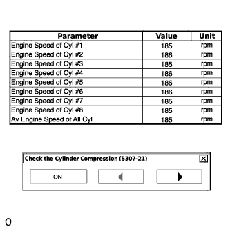
Monitor the engine speed (Engine Speed of Cyl #1 to #8) displayed on the GTS.
Tech Tips
At first, the GTS displays extremely high cylinder engine speed values. After approximately 10 seconds of engine cranking, each cylinder engine speed measurement will change to the actual engine speed.
Note
-
Do not crank the engine continuously for 20 seconds or more.
-
If it is necessary to crank the engine again after Check the Cylinder Compression has been changed to ON and the engine has been cranked once, press Exit to return to the Active Test menu screen. Then change Check the Cylinder Compression to ON and crank the engine.
-
Use a fully-charged battery.
-
-
Stop cranking the engine, and then change "Check the Cylinder Compression" to OFF after the engine stops.
Note
If the Active Test is changed to OFF while the engine is being cranked, the engine will start.
-
Push the snapshot button to turn the snapshot function off.
-
Select "Stored Data" on the GTS screen, select the recorded data and display the data as a graph.
Tech Tips
If the data is not displayed as a graph, the change of the values cannot be observed.
-
Check the change in engine speed values.
Tech Tips
As the data values of the Active Test return to their default values when cranking is stopped, the engine speed value of each cylinder cannot be observed. Therefore, it is necessary to use the data recorded with the snapshot function to check the engine speed values recorded during cranking.
-