СИСТЕМА SFI, Diagnostic DTC:P0171, P0172, P0174, P0175
| DTC Code | DTC Name |
|---|---|
| P0171 | System Too Lean (Bank 1) |
| P0172 | System Too Rich (Bank 1) |
| P0174 | System Too Lean (Bank 2) |
| P0175 | System Too Rich (Bank 2) |
DESCRIPTION
The fuel trim is related to the feedback compensation value, not to the basic injection time. The fuel trim includes the short-term fuel trim and the long-term fuel trim.
The short-term fuel trim is the short-term fuel compensation used to maintain the air-fuel ratio at the stoichiometric air-fuel ratio. The signal from the heated oxygen sensor indicates whether the air-fuel ratio is RICH or LEAN compared to the stoichiometric air-fuel ratio. This variance triggers a reduction in the fuel volume if the air-fuel ratio is RICH, and an increase in the fuel volume if it is LEAN.
The short-term fuel trim varies from the central value due to individual engine differences, wear over time and changes in the operating environment. The long-term fuel trim, which controls overall fuel compensation, steadies long-term deviations of the short-term fuel trim from the central value.
If both the short-term fuel trim and the long-term fuel trim are LEAN or RICH beyond a certain value, the ECM determines this as a malfunction, illuminates the MIL and sets a DTC.
| DTC No. | DTC Detection Condition | Trouble Area |
|---|---|---|
| P0171 P0174 |
When air-fuel ratio feedback is stable after warming up engine, fuel trim is considerably in error on LEAN side (2 trip detection logic) |
|
| P0172 P0175 |
When air-fuel ratio feedback is stable after warming up engine, fuel trim is considerably in error on RICH side (2 trip detection logic) |
|
Tech Tips
-
When DTC P0171 or P0174 is recorded, the actual air-fuel ratio is on the LEAN side. When DTC P0172 or P0175 is recorded, the actual air-fuel ratio is on the RICH side.
-
If the vehicle runs out of fuel, the air-fuel ratio is LEAN and DTC P0171 or P0174 may be recorded. The MIL is then illuminated.
-
If the total of the short-term fuel trim value and long-term fuel trim value is within the malfunction threshold (and ECT is more than 75°C [167°F]), the system is functioning normally.
MONITOR DESCRIPTION
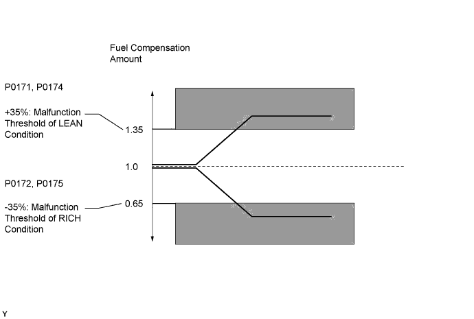
Under closed-loop fuel control, fuel injection amounts that deviate from the ECM's estimated fuel amount will cause a change in the long-term fuel trim compensation value. Long-term fuel trim value is adjusted when persistent deviations in the short-term fuel trim's value are present. Also, the smoothed fuel trim learning value is adjusted when deviations from the ECM's simulated fuel injection value are present. The smoothed fuel trim learning value is a combination of smoothed short-term fuel trim (fuel feedback compensation value) and smoothed long-term fuel trim (learning value of the air-fuel ratio). When the smoothed fuel trim learning value exceeds the malfunction threshold, the ECM interprets this as a fault in the fuel system and sets a DTC.
Example (for Euro OBD):
The smoothed fuel trim learning value is above 35% or below -35%. The ECM interprets this as a fault in the fuel system.
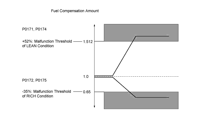
Example (for Brazil OBD Phase 2):
The smoothed fuel trim learning value is above 52% or below -35%. The ECM interprets this as a fault in the fuel system.
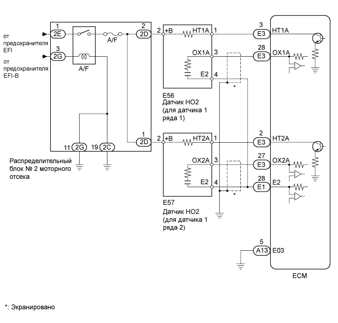
WIRING DIAGRAM
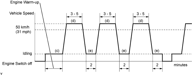
CONFIRMATION DRIVING PATTERN
(a) Connect the GTS to the DLC3.
(b) Switch from normal mode to check mode Click here.
(c) Warm up the engine until the ECT reaches 75°C (167°F).
(d) Drive the vehicle at 50 km/h (31 mph) or more for 3 to 5 minutes.
(e) Allow the engine to idle for 2 minutes.
(f) Perform steps "d" and "e" at least 3 times.
If a malfunction exists, the MIL is illuminated during step "f".
Note
If the conditions in this test are not strictly followed, detection of a malfunction will not occur. If you do not have the GTS, turn the engine switch off after performing steps "c" to "f", and then perform steps "c" to "f" again.
INSPECTION PROCEDURE
Tech Tips
It is possible that the malfunctioning area can be found using the Active Test Control operation. The Active Test can determine if the heated oxygen sensor or other potential trouble areas are malfunctioning or not.
The injection volume can be switched to -12.5% (decrease) or +24.8% (increase) by the Active Test.
The Active Test procedure enables a technician to check and graph the output voltage of the heated oxygen sensors.
-
Procedure:
-
Connect the GTS to the DLC3.
-
Turn the engine switch on (IG).
-
Warm up the engine by running the engine at 2500 rpm for approximately 90 seconds.
-
Enter the following menus: Powertrain / Engine / Active Test / Control the Injection Volume.
-
Perform the Active Test while the engine is idling.
-
Monitor the output voltages of the HO2 sensors (O2S B1S1 and O2S B1S2 or O2S B2S1 and O2S B2S2) displayed on the GTS.
Tech Tips
-
The Control the Injection Volume operation lowers the fuel injection volume by 12.5% or increases the injection volume by 24.8%.
-
Each sensor reacts in accordance with increases and decreases in the fuel injection volume.
| Tester Display | Injection Volume | Status | Voltage |
|---|---|---|---|
| O2S B1S1 or O2S B2S1 | +24.8% | Rich | More than 0.55 V |
| O2S B1S1 or O2S B2S1 | -12.5% | Lean | Less than 0.4 V |
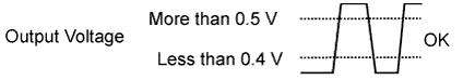
| O2S B1S2 or O2S B2S2 | +24.8% | Rich | More than 0.5 V |
| O2S B1S2 or O2S B2S2 | -12.5% | Lean | Less than 0.4 V |
Note
The heated oxygen sensor (sensor 1) output has a few seconds of delay and the heated oxygen sensor (sensor 2) output has a maximum of 20 seconds of delay.
If the vehicle is short on fuel, the air-fuel ratio becomes LEAN and the DTCs will be recorded.
| Case | Front HO2 Sensor (Sensor 1) Output Voltage | Rear HO2 Sensor (Sensor 2) Output Voltage | Main Suspected Trouble Area |
|---|---|---|---|
| 1 | 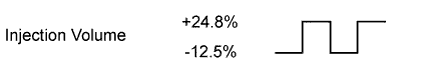 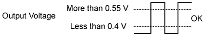 |
 |
- |
| 2 |  |
|
|
| 3 | |
|
|
| 4 | |
|
|
Tech Tips
Read freeze frame data using the GTS. Freeze frame data records the engine conditions when a malfunction is detected. When troubleshooting, freeze frame data can help determine if the vehicle was moving or stationary, if the engine was warmed up or not, if the air-fuel ratio was LEAN or RICH, and other data from the time the malfunction occurred.
A high heated oxygen sensor (sensor 1) voltage (0.55 V or more) indicates a RICH air-fuel ratio.
A low heated oxygen sensor (sensor 1) voltage (0.4 V or less) indicates a LEAN air-fuel ratio.
PROCEDURE
-
CHECK ANY OTHER DTCS OUTPUT (IN ADDITION TO DTC P0171, P0172, P0174 OR P0175)
-
Connect the GTS to the DLC3.
-
Turn the engine switch on (IG) and turn the GTS on.
-
Enter the following menus: Powertrain / Engine / Trouble Codes.
-
Read the DTCs.
Result Display (DTC output) Proceed to P0171, P0172, P0174 or P0175 A P0171, P0172, P0174 or P0175 and other DTCs B Tech Tips
If any DTCs other than P0171, P0172, P0174 or P0175 are output, troubleshoot those DTCs first.
B 
GO TO DTC CHART Click here
A 
-
-
CHECK PCV HOSE CONNECTIONS
-
Check the PCV hose connections.
OK PCV hose is connected correctly and is not damaged.
NG
REPAIR OR REPLACE PCV HOSE
OK
-
-
CHECK AIR INDUCTION SYSTEM
-
Check the air induction system for vacuum leakage.
OK No leakage from air induction system.
NG
REPAIR OR REPLACE AIR INDUCTION SYSTEM
OK
-
-
PERFORM ACTIVE TEST (CONTROL)
-
Perform the Active Test Control with the GTS and check the heated oxygen sensor status.
Tech Tips
-
The Control the Injection Volume operation lowers the fuel injection volume by 12.5% or increases the injection volume by 24.8%.
-
Each sensor reacts in accordance with increases and decreases in the fuel injection volume.
Standard Tester Display Injection Volume Status Voltage O2S B1S1 or O2S B2S1 +24.8% Rich More than 0.55 V O2S B1S1 or O2S B2S1 -12.5% Lean Less than 0.4 V O2S B1S2 or O2S B2S2 +24.8% Rich More than 0.5 V O2S B1S2 or O2S B2S2 -12.5% Lean Less than 0.4 V Result Related DTCs Heated Oxygen Sensor Status Condition and Heated Oxygen Sensor Condition Misfire Main Suspected Trouble Area Go to Step B1S1 B1S2 B2S1 B2S2 N/A L/R L/R L/R L/R Normal None None N/A P0171
P0174
L L L L Actual is LEAN at all cylinders May occur PCV hose, air induction system, fuel pressure, MAF or ECT A P0172
P0175
R R R R Actual is RICH at all cylinders None Fuel pressure, MAF or ECT P0171 L L L/R L/R Actual is LEAN at bank 1 May occur Spark plug, ignition system, injector or exhaust gas leak B P0174 L/R L/R L L Actual is LEAN at bank 2 P0172 R R L/R L/R Actual is RICH at bank 1 None Spark plug, ignition system or injector C P0175 L/R L/R R R Actual is RICH at bank 2 P0171 L R L/R L/R Heated oxygen sensor (bank 1 sensor 1) malfunction None Heated oxygen sensor (bank 1 sensor 1) D P0174 L/R L/R L R Heated oxygen sensor (bank 2 sensor 1) malfunction None Heated oxygen sensor (bank 2 sensor 1) P0172 R L L/R L/R Heated oxygen sensor (bank 1 sensor 1) malfunction None Heated oxygen sensor (bank 1 sensor 1) P0175 L/R L/R R L Heated oxygen sensor (bank 2 sensor 1) malfunction None Heated oxygen sensor (bank 2 sensor 1) Tech Tips
L: During control of the Active Test, the output voltage of the heated oxygen sensor almost always indicates 0.4 V or less (LEAN).
R: During control of the Active Test, the output voltage of the heated oxygen sensor S1 (S2) almost always indicates 0.55 V (0.5 V) or more (RICH).
-
B 
CHECK FOR EXHAUST GAS LEAKAGE Click here
C
INSPECT FUEL INJECTOR Click here
D
INSPECT HEATED OXYGEN SENSOR Click here
A
-
-
READ VALUE USING GTS (COOLANT TEMP)
-
Connect the GTS to the DLC3.
-
Turn the engine switch on (IG) and turn the GTS on.
-
Enter the following menus: Powertrain / Engine / Data List / Coolant Temp.
-
Read the Coolant Temp value when the engine is cold and warmed-up.
Standard ECT when the engine is cold: Same as ambient temperature ECT when the engine is warmed up: 75 to 95°C (167 to 203°F)
NG
REPLACE ENGINE COOLANT TEMPERATURE SENSOR Click here
OK
-
-
READ VALUE USING GTS (MAF Sensor 1, MAF Sensor 2)
-
Connect the GTS to the DLC3.
-
Start the engine and turn the GTS on.
-
Enter the following menus: Powertrain / Engine / Data List / Engine Speed, Coolant Temp, MAF Sensor 1 and MAF Sensor 2.
-
Allow the engine to idle until the ECT reaches 75°C (167°F) or higher.
-
Read MAF Sensor 1 and MAF Sensor 2 with the engine speed at 3000 rpm.
Standard Between 3.6 to 17.6 g/s (shift lever is in N position and A/C is OFF)
NG
CHECK HARNESS AND CONNECTOR Click here
OK
-
-
CHECK FUEL PRESSURE
-
Check the fuel pressure Click here.
NG
REPAIR OR REPLACE FUEL SYSTEM
OK
-
-
CHECK FOR EXHAUST GAS LEAKAGE
-
Check for exhaust gas leakage.
OK No gas leakage.
NG
REPAIR OR REPLACE EXHAUST SYSTEM
OK
-
-
CHECK FOR SPARK AND IGNITION
-
Perform a spark test Click here.
CAUTION:
Always disconnect all the injector connectors.
Note
Do not crank the engine for more than 2 seconds.
OK Spark jumps across electrode gap.
NG
REPAIR OR REPLACE IGNITION SYSTEM
OK
-
-
INSPECT FUEL INJECTOR
-
Check the injector injection and volume Click here.
NG
REPLACE FUEL INJECTOR Click here
OK
-
-
INSPECT HEATED OXYGEN SENSOR
-
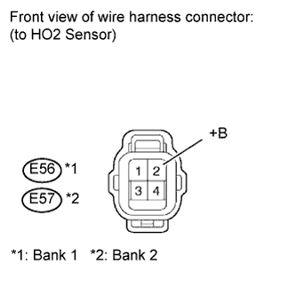
Disconnect the E56 and E57 sensor connectors.
-
Measure the resistance according to the value(s) in the table below.
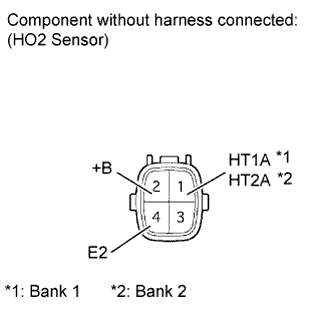
Standard resistance Tester Connection Condition Specified Condition 1 (HT1A) - 2 (+B) Always 11 to 16 Ω 1 (HT2A) - 2 (+B) Always 11 to 16 Ω 1 (HT1A) - 4 (E2) Always 10 kΩ or higher 1 (HT2A) - 4 (E2) Always 10 kΩ or higher
NG
REPLACE HEATED OXYGEN SENSOR Click here
OK
-
-
CHECK HARNESS AND CONNECTOR (HEATER POWER SOURCE)
-
Disconnect the E56 and E57 sensor connectors.
-
Turn the engine switch on (IG).
-
Measure the voltage according to the value(s) in the table below.
Standard voltage Terminal Connections Switch Condition Specified Condition E56-2 (+B) - Body ground Engine switch on (IG) 11 to 14 V E57-2 (+B) - Body ground Engine switch on (IG) 11 to 14 V
NG
CHECK HEATED OXYGEN SENSOR POWER SOURCE CIRCUIT Click here
OK
-
-
CHECK HARNESS AND CONNECTOR (HEATED OXYGEN SENSOR (SENSOR 1) - ECM)
-
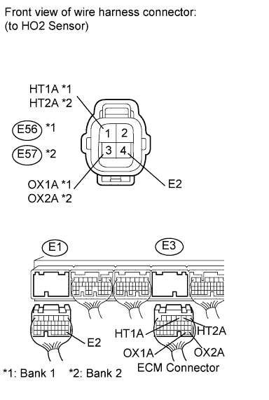
Disconnect the E56 and E57 sensor connectors.
-
Disconnect the E1 and E3 ECM connectors.
-
Measure the resistance according to the value(s) in the table below.
Standard resistance Tester Connection Condition Specified Condition E56-1 (HT1A) - E3-3 (HT1A) Always Below 1 Ω E56-3 (OX1A) - E3-28 (OX1A) Always Below 1 Ω E57-1 (HT2A) - E3-2 (HT2A) Always Below 1 Ω E57-3 (OX2A) - E3-27 (OX2A) Always Below 1 Ω E56-4 (E2) - E1-28 (E2) Always Below 1 Ω E57-4 (E2) - E1-28 (E2) Always Below 1 Ω E56-1 (HT1A) or E3-3 (HT1A) - Body ground Always 10 kΩ or higher E56-3 (OX1A) or E3-28 (OX1A) - Body ground Always 10 kΩ or higher E57-1 (HT2A) or E3-2 (HT2A) - Body ground Always 10 kΩ or higher E57-3 (OX2A) or E3-27 (OX2A) - Body ground Always 10 kΩ or higher
NG
REPAIR OR REPLACE HARNESS AND CONNECTOR
OK
-
-
REPLACE HEATED OXYGEN SENSOR
-
Replace the heated oxygen sensor Click here.
NEXT
-
-
CHECK WHETHER DTC OUTPUT RECURS
-
Connect the GTS to the DLC3.
-
Turn the engine switch on (IG) and turn the GTS on.
-
Clear the DTCs Click here.
-
Turn the engine switch off.
-
Turn the engine switch on (IG) and turn the GTS on.
-
Start the engine and warm it up.
-
Drive the vehicle in accordance with the driving pattern described in the Confirmation Driving Pattern.
-
Enter the following menus: Powertrain / Engine / Trouble Codes.
-
Read the pending DTCs.
Result Display (DTC output) Proceed to DTC P0171, P0172, P0174 or P0175 A No DTC B
B
END
A
-
-
CHECK HARNESS AND CONNECTOR
-
Check the connection and terminal contact pressure of connectors and wire harnesses between the mass air flow meter and ECM Click here.
Tech Tips
Repair any problems.
NEXT
-
-
CHECK WHETHER DTC OUTPUT RECURS
-
Connect the GTS to the DLC3.
-
Turn the engine switch on (IG) and turn the GTS on.
-
Clear the DTCs Click here.
-
Turn the engine switch off.
-
Turn the engine switch on (IG) and turn the GTS on.
-
Start the engine and warm it up.
-
Drive the vehicle in accordance with the driving pattern described in the Confirmation Driving Pattern.
-
Enter the following menus: Powertrain / Engine / Trouble Codes.
-
Read the pending DTCs.
Result Display (DTC output) Proceed to DTC P0171, P0172, P0174 or P0175 A No DTC B
B
END
A
-
-
CHECK HARNESS AND CONNECTOR (MASS AIR FLOW METER - ECM)
-
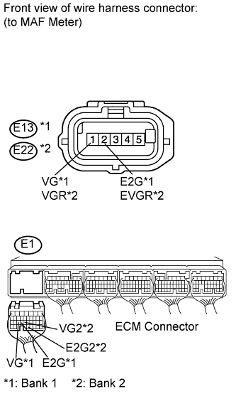
Disconnect the E13 and E22 MAF meter connectors.
-
Disconnect the E1 ECM connector.
-
Measure the resistance according to the value(s) in the table below.
Standard resistance (Check for open) Tester Connection Condition Specified Condition E13-1 (VG) - E1-25 (VG) Always Below 1 Ω E13-2 (E2G) - E1-24 (E2G) Always Below 1 Ω E22-1 (VGR) - E1-23 (VG2) Always Below 1 Ω E22-2 (EVGR) - E1-32 (E2G2) Always Below 1 Ω Standard resistance (Check for short) Tester Connection Condition Specified Condition E13-1 (VG) or E1-25 (VG) - Body ground Always 10 kΩ or higher E22-1 (VGR) or E1-23 (VG2) - Body ground Always 10 kΩ or higher
NG
REPAIR OR REPLACE HARNESS AND CONNECTOR
OK
-
-
REPLACE MASS AIR FLOW METER
-
Replace the mass air flow meter Click here.
Tech Tips
If the result of the inspection performed in step 6 indicated no problem, proceed to the next step without replacing the mass air flow meter.
NEXT
-
-
CONFIRM WHETHER MALFUNCTION HAS BEEN SUCCESSFULLY REPAIRED
-
Connect the GTS to the DLC3.
-
Turn the engine switch on (IG) and turn the GTS on.
-
Clear the DTCs Click here.
-
Turn the engine switch off.
-
Turn the engine switch on (IG) and turn the GTS on.
-
Start the engine and warm it up.
-
Drive the vehicle in accordance with the driving pattern described in the Confirmation Driving Pattern.
-
Enter the following menus: Powertrain / Engine / Trouble Codes.
-
Read the pending DTCs.
Result Display (DTC output) Proceed to No DTC A DTC P0171, P0172, P0174 or P0175 B
B
REPLACE ECM Click here
A 
END
-