LIN COMMUNICATION SYSTEM, Diagnostic DTC:B1492/92

| DTC Code | DTC Name |
|---|---|
| B1492/92 | Infrared Ray Sensor Communication Malfunction |
DESCRIPTION
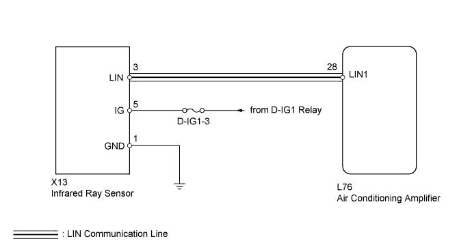
This circuit consists of the infrared ray sensor and the air conditioning amplifier. The infrared ray sensor, which is installed on the rear roof, detects human body temperature and controls the heater and air conditioner "AUTO" mode in 4 zone. Signals are transmitted to the air conditioning amplifier via LIN communication line. This DTC is output when LIN communication between the infrared ray sensor and air conditioning amplifier stop for 10 seconds or more. If the LIN communication system malfunctions, the air conditioning amplifier does not operate even if the infrared ray sensor is normal.
| DTC Code | DTC Detection Condition | Trouble Area |
|---|---|---|
| B1492/92 | Open in LIN communication line |
|
WIRING DIAGRAM
INSPECTION PROCEDURE
Note
Inspect the fuses for circuits related to this system before performing the following inspection procedure.
PROCEDURE
-
CHECK HARNESS AND CONNECTOR (INFRARED RAY SENSOR - AIR CONDITIONING AMPLIFIER)
-
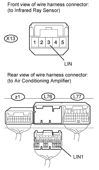
Disconnect the X13 infrared ray sensor connector.
-
Disconnect the L76 air conditioning amplifier connector.
-
Measure the resistance according to the value(s) in the table below.
Standard resistance Tester Connection Condition Specified Condition X13-3 (LIN) - L76-28 (LIN1) Always Below 1 Ω X13-3 (LIN) - Body ground Always 10 kΩ or higher L76-28 (LIN1) - Body ground Always 10 kΩ or higher
NG 
REPAIR OR REPLACE HARNESS OR CONNECTOR
OK 
-
-
CHECK HARNESS AND CONNECTOR (INFRARED RAY SENSOR - BATTERY AND BODY GROUND)
-
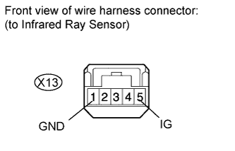
Disconnect the X13 infrared ray sensor connector.
-
Measure the resistance and voltage according to the value(s) in the table below.
Standard resistance Tester Connection Condition Specified Condition X13-1 (GND) - Body ground Always Below 1 Ω Standard voltage Tester Connection Condition Specified Condition X13-5 (IG) - Body ground Power switch OFF Below 1 V X13-5 (IG) - Body ground Power switch ON (IG) 11 to 14 V
NG
REPAIR OR REPLACE HARNESS OR CONNECTOR
OK
-
-
CHECK INFRARED RAY SENSOR (OPERATION)
-
Replace the infrared ray sensor with a new or normally functioning one Click here.
-
Operate the infrared ray sensor to check that it functions normally.
OK Infrared ray sensor function operates normally.
NG
REPLACE AIR CONDITIONING AMPLIFIER Click here
OK 
END (INFRARED RAY SENSOR IS FAULTY)
-