DESCRIPTION
This DTC is output when LIN communication between the master switch assembly and main body ECU stops for 10 seconds or more.
| DTC Code | DTC Detection Condition | Trouble Area |
|---|---|---|
| B1206 | No communication between master switch assembly and main body ECU for 10 seconds or more |
|
INSPECTION PROCEDURE
When using the intelligent tester with the power switch OFF to troubleshoot:
Connect the intelligent tester to the vehicle, and turn a courtesy switch on and off at 1.5 second intervals until communication between the tester and vehicle begins.
DTC B2325 is output when the communication between all of the following components and main body ECU stops.
PROCEDURE
- Click here
CLEAR DTC
-
Clear the DTC (see pageClick here).
- NEXTClick here
-
- Click here
CHECK FOR DTC
-
Recheck for DTC (see pageClick here).
Table 1. Result: Result Proceed to DTC B1206 output reoccurs A DTC B1206 output does not reoccur B
-
-
Click here
CHECK HARNESS AND CONNECTOR (MAIN BODY ECU - MASTER SWITCH)
-
Disconnect the L11 ECU connector.
-
Disconnect the N13 switch connector.
-
Measure the resistance according to the value(s) in the table below.
Standard resistance Tester Connection Condition Specified Condition L11-10 (LIN2) - N13-17 (LIN1) Always Below 1 Ω L11-10 (LIN2) or N13-17 (LIN1) - Body ground Always 10 kΩ or higher
- OKClick here
- NGClick here
-
- Click here
CHECK HARNESS AND CONNECTOR (MASTER SWITCH - BATTERY AND BODY GROUND)
-
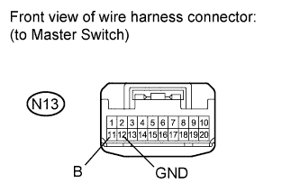
Disconnect the N13 switch connector.
-
Measure the resistance and voltage according to the value(s) in the table below.
Standard resistance Tester Connection Condition Specified Condition N13-12 (GND) - Body ground Always Below 1 Ω Standard voltage Tester Connection Condition Specified Condition N13-11 (B) - Body ground Always 11 to 14 V
- OKClick here
- NGClick here
-
- Click here
CHECK MASTER SWITCH ASSEMBLY (OPERATION)
-
Temporarily replace the master switch assembly with a new or normally functioning one (see pageClick here).
-
Clear the DTC (see pageClick here).
- NEXTClick here
-
- Click here
CHECK FOR DTC
-
Recheck for DTC (see pageClick here).
Table 2. Result: Result Proceed to DTC B1206 output does not reoccur A DTC B1206 output reoccurs B
-
- Click here
USE SIMULATION METHOD TO CHECKClick here
- Click here
REPAIR OR REPLACE HARNESS OR CONNECTOR
- Click here
REPAIR OR REPLACE HARNESS OR CONNECTOR
- Click here
REPLACE MAIN BODY ECU
- Click here
END (MASTER SWITCH IS DEFECTIVE)