ROOF HEADLINING (for Long Body) INSTALLATION

Tech Tips
-
Use the same procedure for RHD and LHD vehicles.
-
The procedure listed below is for LHD vehicles.
-
A bolt without a torque specification is shown in the standard bolt chart Click here.
-
INSTALL FRONT DOOR OPENING TRIM WEATHERSTRIP LH
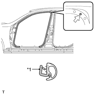
Text in Illustration *1 Paint Mark 
Mark Position
-
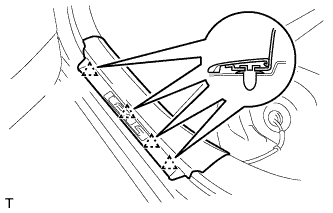
Install the front door opening trim weatherstrip LH as shown in the illustration.
-
-
INSTALL FRONT DOOR OPENING TRIM WEATHERSTRIP RH
Tech Tips
Use the same procedure described for the LH side.
-
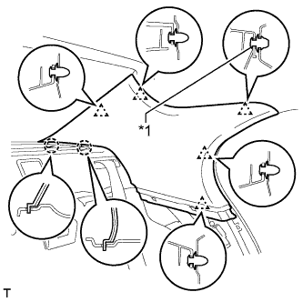
INSTALL REAR DOOR OPENING TRIM WEATHERSTRIP LH
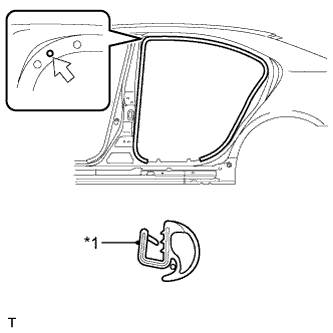
Text in Illustration *1 Paint Mark Mark Position
-
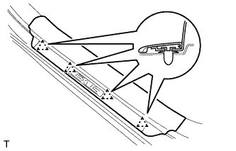
Install the rear door opening trim weatherstrip LH as shown in the illustration.
-
-
INSTALL REAR DOOR OPENING TRIM WEATHERSTRIP RH
Tech Tips
Use the same procedure described for the LH side.
-
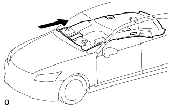
PLACE ROOF HEADLINING ASSEMBLY IN VEHICLE
-
Place the roof headlining assembly into the vehicle through the front side.
Note
Be careful not to damage the roof headlining assembly when placing it in the cabin.
Tech Tips
Place the roof headlining into the vehicle so that the windshield glass can be installed.
-
-
INSTALL WINDSHIELD GLASS
-
INSTALL OBJECT RECOGNITION CAMERA (w/ Lane Keeping Assist System)
Note
-
Do not touch the camera lens when removing or installing the camera.
-
Do not use a camera which has been dropped or subjected to an impact.
-
If the camera is not installed securely, the system may not operate properly. Therefore, be sure to install the camera securely.
-
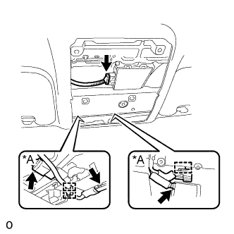
Push the bracket to attach the clip.
-
Allow the wire harness to hang down.
-
Do not press the sensor, as it may become deformed.
-
Temporarily install the object recognition camera with the clip.
-
Install the 3 bolts in alphabetical order.
- Torque:
- 9.0 N*m { 92 kgf*cm, 80 in.*lbf }
-
Attach the claw to connect the connector clamp.
-
Attach the 2 wire harness clamps.
-
Connect the 3 connectors.
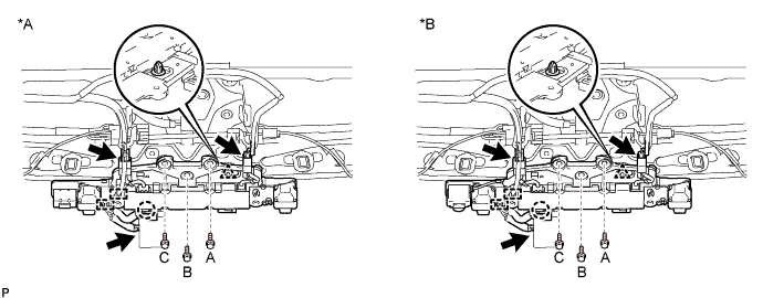
Text in Illustration *A w/o Night View System *B w/ Night View System -
Return the roof headlining to its original position.
-
-
INSTALL INNER REAR VIEW MIRROR ASSEMBLY
-
w/o Automatic High Beam System:
-
w/ Automatic High Beam System:
-
-
INSTALL RAIN SENSOR COVER
-
w/o Lane Keeping Assist System:
-
w/ Lane Keeping Assist System:
-
-
INSTALL ROOF HEADLINING ASSEMBLY
-
w/o Rear Seat Entertainment System:
Attach the hook, 12 claws, 10 fasteners and 4 clips to install the roof headlining assembly.
-
w/ Rear Seat Entertainment System:
Attach the hook, 12 claws, 8 fasteners and 4 clips to install the roof headlining assembly.
-
Text in Illustration *A w/ Lane Keeping Assist System Connect each connector and each wire harness clamp.
-
Connect the roof wire connectors and attach each wire harness clamp.
-
-
INSTALL VISOR HOLDER
Tech Tips
Use the same procedure to install the holder on the other side.
-
Attach the 2 claws to install the visor holder.
-
Push in the visor holder and turn it approximately 45° as shown in the illustration.
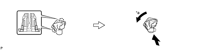
Text in Illustration *a 45° - -
-
-
INSTALL VISOR ASSEMBLY LH
-
Install the visor assembly LH with the 2 screws.
-
-
INSTALL VISOR ASSEMBLY RH
Tech Tips
Use the same procedure described for the LH side.
-
INSTALL VISOR BRACKET COVER
Tech Tips
Use the same procedure to install the visor bracket cover on the other side.
-
Attach the 4 claws to install the visor bracket cover.
-
-
INSTALL ASSIST GRIP SUB-ASSEMBLY
Tech Tips
Use the same procedure for all the assist grips.
-
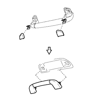
Assemble the assist grip sub-assembly, 2 clips and 2 covers as shown in the illustration.
-
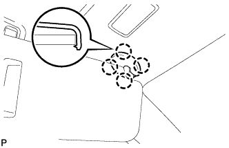
Attach the 2 clips to install the assist grip sub-assembly.
-
-
INSTALL ROOF SIDE REGISTER BEZEL LH
-
Attach the claw to install the roof side register bezel LH.
-
Install the screw.
-
-
INSTALL ROOF SIDE REGISTER BEZEL RH
Tech Tips
Use the same procedure described for the LH side.
-
INSTALL REAR VANITY LIGHT ASSEMBLY
Tech Tips
Use the same procedure to install the vanity light assembly on the other side.
-
Connect the connector.
-
Attach the claw to install the vanity light assembly.
-
Install the 2 screws.
-
Attach the 4 claws to install the lens.
-
-
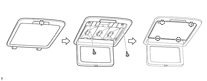
INSTALL SPOT LIGHT ASSEMBLY (w/o Rear Seat Entertainment System)
-
Connect the connector.
-
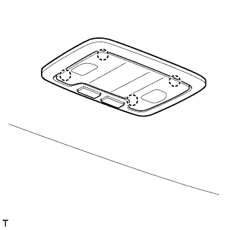
Attach the 4 claws to install the spot light assembly.
-
-
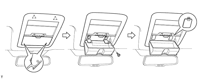
INSTALL ROOF CONSOLE BOX ASSEMBLY (w/ Rear Seat Entertainment System)
-
w/o Infrared Ray Sensor:
Connect the connector.
-
w/ Infrared Ray Sensor:
Connect the 2 connectors.
-
Attach the 6 clips and 2 claws to install the roof console box assembly.
-
Install the 2 screws.
-
-
INSTALL SPOT LIGHT LENS (w/ Rear Seat Entertainment System)
-
Attach the 4 claws to install the spot light lens.
-
-
INSTALL ROOF CONSOLE BOX ASSEMBLY (for 5-Passenger with Ottoman)
-
Connect the 2 connectors.
-
Attach the 2 hooks, 2 clips and 2 claws to install the roof console box assembly.
-
Install the 2 screws.
-
-
INSTALL SPOT LIGHT LENS (for 5-Passenger with Ottoman)
-
Attach the 4 claws to install the spot light lens.
-
-
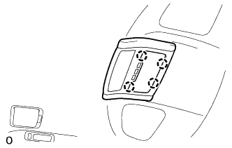
INSTALL MAP LIGHT ASSEMBLY
-
Connect the 2 connectors.
-
Attach the 2 clips to install the map light assembly.
-
Install the 2 screws.
-
Attach the 2 claws to close the 2 covers.
-
-
INSTALL INNER ROOF SIDE GARNISH LH
Text in Illustration *1 Clip A
-
Install a new clip A to the inner roof side garnish LH.
-
Attach the 2 claws and 5 clips to install the inner roof side garnish LH.
-
-
INSTALL INNER ROOF SIDE GARNISH RH
Tech Tips
Use the same procedure described for the LH side.
-
INSTALL REAR SEAT SIDE GARNISH LH
-
Attach the 6 claws to install the rear seat side garnish LH.
-
-
INSTALL REAR SEAT SIDE GARNISH RH
Tech Tips
Use the same procedure described for the LH side.
-
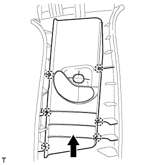
INSTALL SHOULDER BELT ANCHOR COVER LH
-
Slide the shoulder belt anchor cover LH in the direction shown in the illustration and attach the 6 claws to install it.
-
-
INSTALL SHOULDER BELT ANCHOR COVER RH
Tech Tips
Use the same procedure described for the LH side.
-
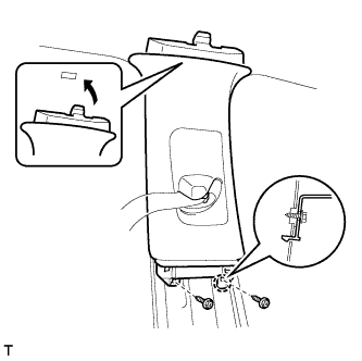
INSTALL CENTER UPPER PILLAR GARNISH LH
-
Pass the front seat outer belt floor anchor through the center upper pillar garnish LH.
-
Attach the guide and claw to install the center upper pillar garnish LH.
-
Install the 2 screws.
-
-
INSTALL CENTER UPPER PILLAR GARNISH RH
Tech Tips
Use the same procedure described for the LH side.
-
INSTALL CENTER LOWER PILLAR GARNISH LH
-
Attach the 2 claws and 6 clips to install the center lower pillar garnish LH.
-
-
INSTALL CENTER LOWER PILLAR GARNISH RH
Tech Tips
Use the same procedure described for the LH side.
-
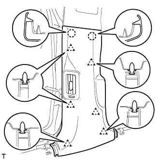
INSTALL REAR DOOR SCUFF PLATE LH
-
Attach the 4 clips.
-
Attach the 7 claws to install the rear door scuff plate LH.
-
-
INSTALL REAR DOOR SCUFF PLATE RH
Tech Tips
Use the same procedure described for the LH side.
-
INSTALL FRONT PILLAR GARNISH LH
-
Attach the guide.
-
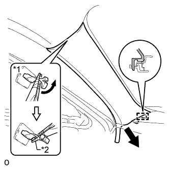
Turn the end of the front pillar garnish clip 90° with needle-nose pliers and install it to the front pillar garnish LH.
Tech Tips
Tape the tips of the needle-nose pliers before use.
Text in Illustration *1 Front Pillar Garnish Clip *2 Protective Tape -
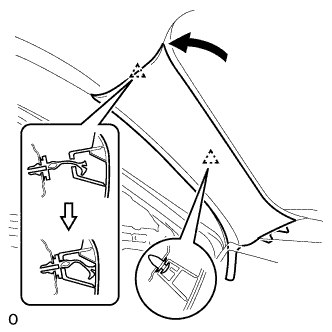
Attach the 2 clips to install the front pillar garnish LH.
Note
After installing the front pillar garnish LH, make sure that the lip of the front door opening trim weatherstrip LH is not pinched.
-
-
INSTALL FRONT PILLAR GARNISH RH
Tech Tips
Use the same procedure described for the LH side.
-
INSTALL COWL SIDE TRIM BOARD LH
-
Attach the 3 claws to install the cowl side trim board LH.
-
-
INSTALL COWL SIDE TRIM BOARD RH
Tech Tips
Use the same procedure described for the LH side.
-
INSTALL FRONT DOOR SCUFF PLATE LH
-
Attach the 4 clips.
-
Attach the 7 claws to install the front door scuff plate LH.
-
-
INSTALL FRONT DOOR SCUFF PLATE RH
Tech Tips
Use the same procedure described for the LH side.
-
INSTALL FRONT SEAT ASSEMBLY
-
INSTALL REAR SEAT ASSEMBLY (for Fixed Type)
-
INSTALL REAR SEAT ASSEMBLY (for Power Seat)
-
INSTALL REAR SEAT ASSEMBLY (for 4-Passenger with Ottoman)
-
INSTALL REAR SEAT ASSEMBLY (for 5-Passenger with Ottoman)
-
CONNECT CABLE TO AUXILIARY BATTERY NEGATIVE TERMINAL
Note
When disconnecting the cable, some systems need to be initialized after the cable is reconnected Click here.
-
CHECK SRS WARNING LIGHT
-
ADJUST OBJECT RECOGNITION CAMERA (w/ Lane Keeping Assist System)
-
INSTALL BATTERY SERVICE HOLE COVER LH
-

Text in Illustration *A for Standard *B for Ottoman Attach the battery service hole cover LH with the clip and fastening tape.
-
-
INSTALL DECK TRIM SIDE BOARD LH (w/o Spare Tire)
-

Attach the 2 clips to install the deck trim side board LH.
-
-
INSTALL DECK BOARD ASSEMBLY (w/o Spare Tire)

-
INSTALL LUGGAGE COMPARTMENT MAT SUB-ASSEMBLY (w/ Spare Tire)
