FRONT DOOR BELT MOULDING REMOVAL

Tech Tips
-
Use the same procedure for the RH side and LH side.
-
The procedure listed below is for the LH side.
-
PRECAUTION
Note
After turning the power switch off, waiting time may be required before disconnecting the cable from the auxiliary battery negative (-) terminal. Therefore, make sure to read the disconnecting the cable from the auxiliary battery negative (-) terminal notices before proceeding with work Click here.
-
REMOVE LUGGAGE COMPARTMENT MAT SUB-ASSEMBLY (w/ Spare Tire)

-
REMOVE DECK BOARD ASSEMBLY (w/o Spare Tire)

-
REMOVE DECK TRIM SIDE BOARD LH (w/o Spare Tire)
-

Detach the 2 clips and remove the deck trim side board LH.
-
-
REMOVE BATTERY SERVICE HOLE COVER LH
-

Text in Illustration *A for Standard *B for Ottoman *1 Fastening Tape Detach the clip, fastening tape and remove the battery service hole cover LH.
-
-
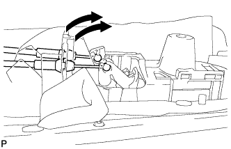
DISCONNECT CABLE FROM AUXILIARY BATTERY NEGATIVE TERMINAL
CAUTION:
Wait at least 90 seconds after disconnecting the cable from the negative (-) battery terminal to disable the SRS system.
Note
When disconnecting the cable, some systems need to be initialized after the cable is reconnected Click here.
-
REMOVE FRONT DOOR INSIDE HANDLE BEZEL PLUG LH
-
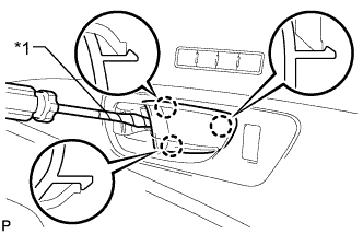
Text in Illustration *1 Protective Tape Using a screwdriver, detach the 3 claws and remove the front door inside handle bezel plug LH.
Tech Tips
Tape the screwdriver tip before use.
-
-
REMOVE POWER WINDOW REGULATOR MASTER SWITCH ASSEMBLY WITH FRONT DOOR ARMREST BASE PANEL
-
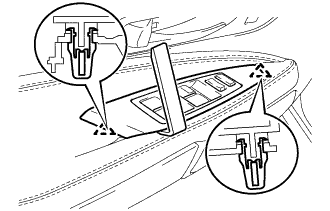
Using a moulding remover D, detach the 2 clips.
-
Disconnect the connector and remove the power window regulator master switch assembly with front door armrest base panel.
Tech Tips
Tape the screwdriver tip before use.
-
-
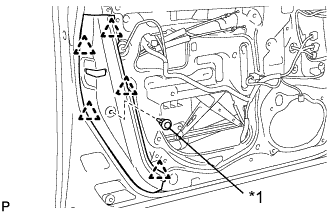
REMOVE FRONT DOOR TRIM BOARD SUB-ASSEMBLY LH
-
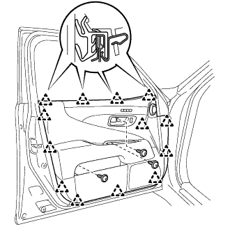
Remove the 3 screws.
-
Detach the 13 clips and remove the front door trim board sub-assembly LH.
-
Disconnect the connector.
-
Disconnect the 2 cables from the inside handle.
-
-
REMOVE FRONT MULTIPLEX NETWORK DOOR ECU LH
-
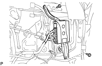
Remove the 2 screws and front multiplex network door ECU LH.
-
Disconnect the 3 connectors.
-
-
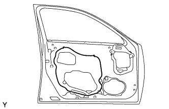
REMOVE FRONT DOOR NO. 2 SERVICE HOLE COVER LH
-
Remove the front door No. 2 service hole cover LH.
Tech Tips
Remove the remaining tape on the door.
-
-
REMOVE OUTER REAR VIEW MIRROR ASSEMBLY LH
-
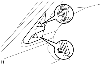
REMOVE FRONT DOOR GLASS INNER WEATHERSTRIP LH
-
Remove the front door glass inner weatherstrip LH by pulling it upward in the direction indicated by the arrow in the illustration.
-
-
REMOVE FRONT DOOR TRIM COVER LH
-
Text in Illustration *1 Cushion Remove the cushion.
-
Using a clip remover, detach the 5 clips.
-
-
REMOVE DOOR FRAME GARNISH LH
-
Remove the 2 clips and door frame garnish LH.
-
-
REMOVE FRONT DOOR BELT MOULDING REAR END COVER LH
-
Detach the claw and front door belt moulding end cover rear LH.
-
-
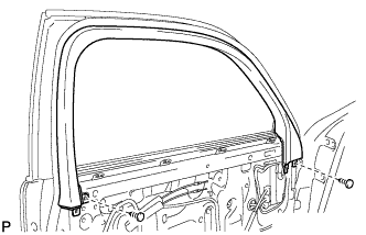
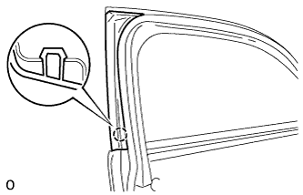
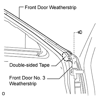
REMOVE FRONT DOOR WEATHERSTRIP LH
-
Remove the clip and front door weatherstrip.
Tech Tips
Lift up the front door No. 3 weatherstrip to remove the front door No. 2 weatherstrip, as the No. 2 weatherstrip is affixed to the inner side of the No. 3 weatherstrip.
-
-
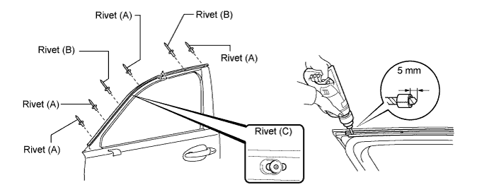
REMOVE FRONT DOOR WINDOW FRONT FRAME MOULDING LH
-
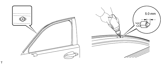
Put a 4 mm (0.157 in.) drill bit into a drill.
-
Wind tape around the drill bit approximately 5 mm (0.197 in.) from the tip of the drill, as shown in the illustration.
Tech Tips
Tape the 4 mm (0.157 in.) drill bit to prevent the drill bit from going too deep.
-
Lightly press the drill against each of the 6 front door window frame moulding rivets labeled (A) and (B) shown in the illustration, and drill off each rivet's flange.
Tech Tips
-
The rivets labeled (A) are the installation rivets of the front door window frame moulding.
-
The rivets labeled (B) are the installation rivets for both the front door window frame moulding and front door belt moulding.
-
Do not remove the front door window belt moulding's rivet labeled (C).
Note
-
Pressing the drill too firmly will cause the rivet to turn and result in the rivet not being drilled through.
-
Do not pry the rivets with the drill, because this may cause damage to the installation holes of the rivets or the drill bit.
-
Be careful of the drilled rivets as they may become hot.
-
-
Using a vacuum cleaner, remove the rivet fragments and shavings from the drilled areas.
-
Detach the clip and remove the window frame moulding.
-
-
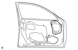
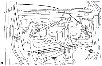
REMOVE FRONT DOOR SERVICE HOLE COVER LH
-
Remove the front door service hole cover LH.
Tech Tips
Remove the remaining tape on the door.
-
-
REMOVE FRONT DOOR GLASS SUB-ASSEMBLY LH
-
Connect the front door ECU LH.
-
Temporarily install the power window regulator master switch assembly with front door armrest base panel.
-
Connect the cable to the negative (-) battery terminal.
-
Remove the hole plug.
-
Move the front window regulator sub-assembly LH so that the front door glass sub-assembly LH bolts can be seen.
-
Disconnect the cable from the negative (-) battery terminal.
Note
When disconnecting the cable, some systems need to be initialized after the cable is reconnected Click here.
-
Remove the 2 bolts.
Note
Be careful when removing the bolts as the glass may fall and become damaged.
-
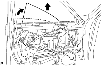
Remove the front door glass sub-assembly in the direction indicated by the arrows in the illustration.
Tech Tips
Remove the glass upward.
Note
Be careful not to damage the glass.
-
Remove the power window regulator master switch assembly with front door armrest base panel.
-
Disconnect the front door ECU LH.
-
-
REMOVE FRONT DOOR GLASS RUN LH
-
Remove the front door glass run LH.
-
-
REMOVE FRONT DOOR FRONT LOWER FRAME UPPER COVER LH
-
Detach the 2 clips and remove the front door front lower frame upper cover LH.
-
-
REMOVE FRONT DOOR BELT MOULDING SUB-ASSEMBLY LH
-
Put a 4.5 mm (0.177 in.) drill bit into a drill.
-
Wind tape around the drill bit approximately 5 mm (0.197 in.) from the tip of the drill as shown in the illustration.
-
Lightly press the drill against the rivet shown in the illustration, and drill off the rivet's flange.
CAUTION:
Be careful of the drilled rivet as it may become hot.
Note
-
Pressing the drill too firmly will cause the rivet to turn and result in the rivet not being drilled through.
-
Do not pry the rivet with the drill, because this may cause damage to the installation holes of the rivet or the drill bit.
-
-
Using a vacuum cleaner, remove the rivet fragments and shavings from the drilled area.
-
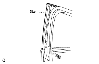
Remove the 2 screws.
-
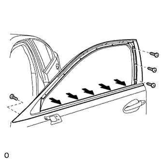
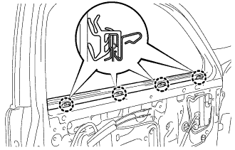
for Type A:
-
Loosen the 5 belt line screws indicated by the arrows in the illustration.
-
Remove the 4 screws and front door sub-assembly LH.
-
-
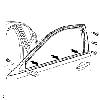
for Type B:
-
Loosen the 3 belt line screws indicated by the arrows in the illustration.
-
Remove the 4 screws and front door sub-assembly LH.
-
-