LUGGAGE COMPARTMENT DOOR OPENER OUTER SWITCH INSTALLATION

-
INSTALL LUGGAGE ELECTRICAL KEY SWITCH
-
Install the television camera assembly to the luggage electrical key switch with the 2 screws.
-
Connect the connector.
-
Connect the sub-wire harness connector.
-
-
INSTALL LUGGAGE COMPARTMENT DOOR OUTSIDE GARNISH SUB-ASSEMBLY
-
Attach the 6 clips to install the luggage compartment door outside garnish.
-
Install the 6 screws.
-
-
INSTALL NO. 3 LUGGAGE COMPARTMENT DOOR OUTSIDE GARNISH
-
Attach the 4 claws to install the No. 3 luggage compartment door outside garnish.
-
-
INSTALL REAR LIGHT ASSEMBLY LH
-
w/o Rear Fog Light:
-
Install the rear light assembly LH with the 2 nuts and 2 cap nuts.
- Torque:
- 4.5 N*m { 46 kgf*cm, 40 in.*lbf }
-
Connect the connector.
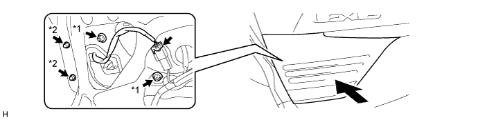
Text in Illustration *1 Nut *2 Cap Nut
-
-
w/ Rear Fog Light:
-
Install the rear light assembly LH with the 2 nuts and 2 cap nuts.
- Torque:
- 4.5 N*m { 46 kgf*cm, 40 in.*lbf }
-
Connect the connector.
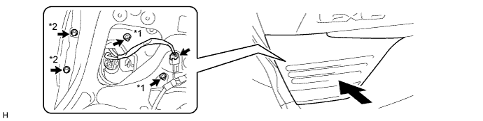
Text in Illustration *1 Nut *2 Cap Nut
-
-
-
INSTALL REAR LIGHT ASSEMBLY RH
Tech Tips
Use the same procedure described for the LH side.
-
INSTALL BACK DOOR TRIM COVER
-
Attache the 10 clips to install the back door trim cover.
-
Install the 4 clips.
-
-
INSTALL LUGGAGE COMPARTMENT DOOR HINGE COVER RH
Tech Tips
Use the same procedure described for the LH side.
-
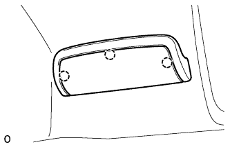
INSTALL LUGGAGE COMPARTMENT DOOR HINGE COVER LH
-
Install the luggage compartment door hinge cover LH with the 3 clips.
-
-
INSTALL REAR COMBINATION LIGHT SERVICE COVER RH
Tech Tips
Use the same procedure described for the LH side.
-
INSTALL REAR COMBINATION LIGHT SERVICE COVER LH
-
Attach the 3 claws to install the rear combination light service cover LH.
-
-
INSTALL NO. 2 COURTESY LIGHT ASSEMBLY
-
Connect the connector.
-
Attach the 2 claws to install the No. 2 courtesy light assembly.
-
-
INSTALL SWITCH BEZEL
-
Attach the 2 claws to install the switch bezel.
-
-
INSTALL LUGGAGE COMPARTMENT DOOR ASSIST GRIP
-
Install the luggage compartment door assist grip with the 2 screws.
-
Attach the 3 claws.
-
-
CONNECT CABLE TO AUXILIARY BATTERY NEGATIVE TERMINAL
Note
When disconnecting the cable, some systems need to be initialized after the cable is reconnected Click here.
-
INSTALL BATTERY SERVICE HOLE COVER LH
-

Text in Illustration *A for Standard *B for Ottoman Attach the battery service hole cover LH with the clip and fastening tape.
-
-
INSTALL DECK TRIM SIDE BOARD LH (w/o Spare Tire)
-

Attach the 2 clips to install the deck trim side board LH.
-
-
INSTALL DECK BOARD ASSEMBLY (w/o Spare Tire)

-
INSTALL LUGGAGE COMPARTMENT MAT SUB-ASSEMBLY (w/ Spare Tire)

-
ADJUST REAR TELEVISION CAMERA ASSEMBLY (w/ Parking Assist Monitor System)