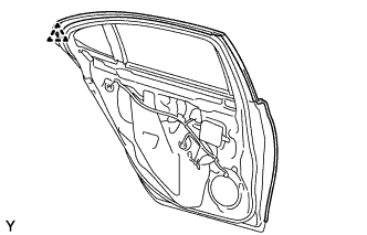
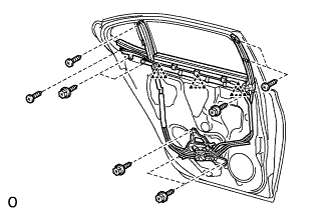
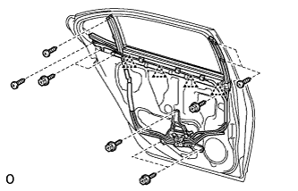
REAR DOOR REMOVAL

Tech Tips
-
Use the same procedure for the RH and LH sides.
-
The procedure listed below is for the LH side.
-
PRECAUTION
Note
After turning the power switch off, waiting time may be required before disconnecting the cable from the auxiliary battery terminal. Therefore, make sure to read the disconnecting the cable from the auxiliary battery terminal notice before proceeding with work Click here.
-
REMOVE LUGGAGE COMPARTMENT MAT SUB-ASSEMBLY (w/ Spare Tire)

-
REMOVE DECK BOARD ASSEMBLY (w/o Spare Tire)

-
REMOVE DECK TRIM SIDE BOARD LH (w/o Spare Tire)
-

Detach the 2 clips and remove the deck trim side board LH.
-
-
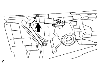
REMOVE BATTERY SERVICE HOLE COVER LH
-

Text in Illustration *A for Standard *B for Ottoman *1 Fastening Tape Detach the clip, fastening tape and remove the battery service hole cover LH.
-
-
DISCONNECT CABLE FROM AUXILIARY BATTERY NEGATIVE TERMINAL
Note
When disconnecting the cable, some systems need to be initialized after the cable is reconnected Click here.
-
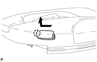
REMOVE REAR DOOR INSIDE HANDLE BEZEL PLUG LH
-
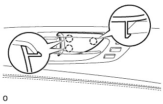
Using a screwdriver, detach the 3 claws and remove the rear door inside handle bezel plug LH.
Tech Tips
Tape the screwdriver tip before use.
-
-
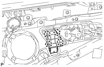
REMOVE REAR POWER WINDOW REGULATOR SWITCH ASSEMBLY WITH REAR DOOR ARMREST BASE PANEL

-
Apply protective tape to the area around the rear power window regulator switch assembly with rear door armrest base panel.
-
Using a clip remover, detach the 2 clips in the order shown in the illustration.
Text in Illustration *1 Protective Tape -
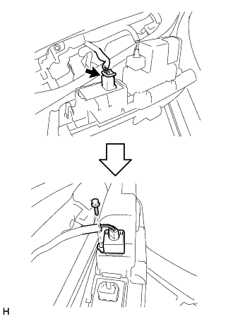
Disconnect the connector.
-
Remove the screw and illumination light.
-
Remove the rear power window regulator switch assembly with rear door armrest base panel.
-
-
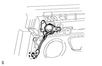
REMOVE ROOM TEMPERATURE SENSOR (w/ Rear Cooler)
-
Using a screwdriver, detach the 4 claws and remove cooler thermistor, and then disconnect the connector.
-
-
REMOVE REAR DOOR TRIM BOARD SUB-ASSEMBLY LH (w/o Rear Door Sunshade)
-
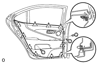
for Long Body:
-
Remove the 3 screws.
-
Detach the 13 clips.
Note
Do not use a tool to detach the clips of the rear door trim board sub-assembly LH.
-
Disconnect the 2 cables from the inside handle.
-
Disconnect the connectors and remove the trim board.
-
-
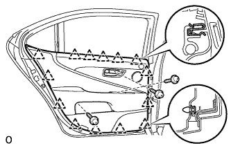
for Standard Body:
-
Remove the 3 screws.
-
Detach the 11 clips.
Note
Do not use a tool to detach the clips of the rear door trim board sub-assembly LH.
-
Disconnect the 2 cables from the inside handle.
-
Disconnect the connectors and remove the trim board.
-
-
-
REMOVE REAR DOOR TRIM BOARD SUB-ASSEMBLY LH (w/ Rear Door Sunshade)
-
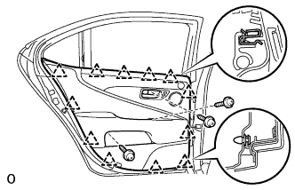
for Long Body:
-
Remove the 3 screws.
-
Detach the 14 clips.
Note
Do not use a tool to detach the clips of the rear door trim board sub-assembly LH.
-
Disconnect the 2 cables from the inside handle.
-
Disconnect the connectors and remove the rear door trim board sub-assembly LH.
-
-
for Standard Body:
-
Remove the 3 screws.
-
Detach the 12 clips.
Note
Do not use a tool to detach the clips of the rear door trim board sub-assembly LH.
-
Disconnect the 2 cables from the inside handle.
-
Disconnect the connectors and remove the rear door trim board sub-assembly LH.
-
-
-
REMOVE REAR DOOR INSIDE HANDLE ILLUMINATION LIGHT ASSEMBLY LH
-
Detach the claw, disconnect the connector and then remove the light.
-
-
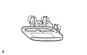
REMOVE COURTESY LIGHT ASSEMBLY
-
Detach the claw.
-
Disconnect the connector and remove the courtesy light assembly.
-
-
REMOVE REAR SEAT MEMORY SWITCH (w/ Rear Seat Memory System)
-
Disconnect the connector.
-
Detach the 4 claws to remove the rear seat memory switch.
-
-
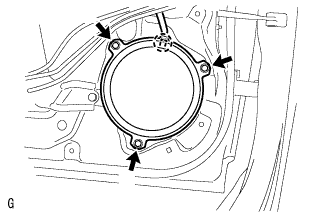
REMOVE REAR NO. 3 SPEAKER ASSEMBLY (for 19 Speakers)
Note
Do not touch the cone of the speaker.
-
Disconnect the connector.
-
Detach the clamp, and remove the 2 screws and rear No. 3 speaker assembly.
-
-
REMOVE REAR DOOR TRIM COVER LH
-
Remove the cushion.
-
Using a clip remover, detach the 5 clips and remove the rear door trim cover LH.
-
-
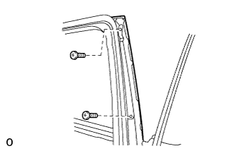
REMOVE REAR DOOR FRAME GARNISH LH
-
w/o Rear Door Sunshade:
-
Remove the screw and detach the clip.
-
Detach the claws and remove the rear door frame garnish LH.
-
-
w/ Rear Door Sunshade:
-
Detach the 2 clips.
-
Detach the claws and remove the rear door frame garnish LH.
-
-
-
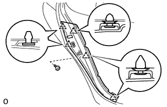
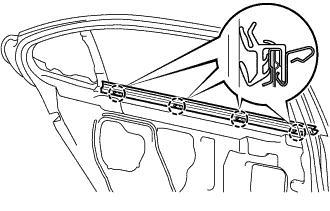
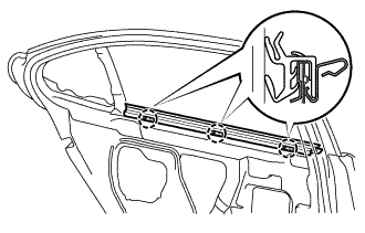
REMOVE REAR DOOR NO. 3 WEATHERSTRIP LH
-
Text in Illustration *1 Double-sided Tape Detach the 2 claws and remove the rear door No. 3 weatherstrip LH.
-
-
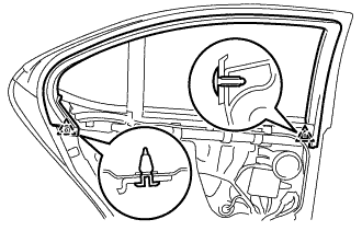
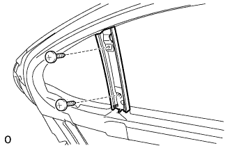
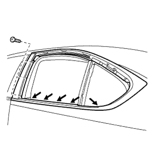
REMOVE REAR DOOR NO. 2 FRAME GARNISH LH
-
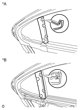
Text in Illustration *A w/o Rear Door Sunshade *B w/ Rear Door Sunshade Detach the claws and remove the rear door No. 2 frame garnish LH.
-
-
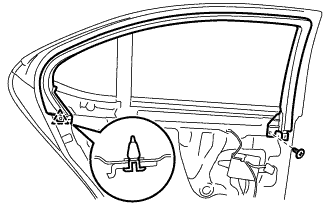
REMOVE REAR DOOR NO. 2 WEATHERSTRIP LH
-
Detach the clip and remove the rear door No. 2 weatherstrip LH.
-
-
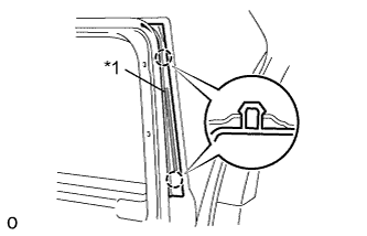
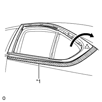
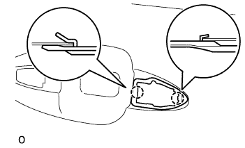
REMOVE REAR ACCESS PANEL WEATHERSTRIP LH
-
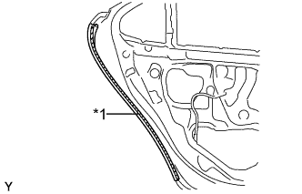
Text in Illustration *1 Double-sided Tape Remove the rear access panel weatherstrip LH.
-
-
REMOVE REAR CURTAIN SUB-ASSEMBLY LH (w/ Rear Door Sunshade)
-
for Standard Body:
-
Remove the 10 screws.
-
Detach the 3 clips and remove the rear curtain sub-assembly LH.
-
Disconnect the connector
-
-
for Long Body:
-
Remove the 10 screws.
-
Detach the 4 clips and remove the rear curtain sub-assembly LH.
-
Disconnect the connector
-
-
-
REMOVE NO. 1 AUTO CURTAIN RAIL BRACKET LH (w/ Rear Door Sunshade)
-
Using a clip remover, detach the clip and remove the No. 1 auto curtain rail bracket LH.
-
-
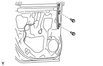
REMOVE REAR SIDE TRIM BOARD COVER LH (w/ Rear Door Sunshade)
-
Remove the 2 screws and rear side trim board cover LH.
-
-
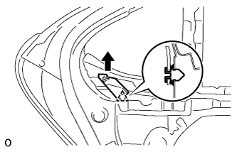
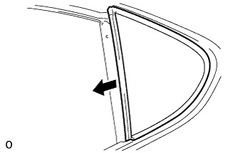
REMOVE REAR DOOR GLASS INNER WEATHERSTRIP LH
-
for Long Body:
-
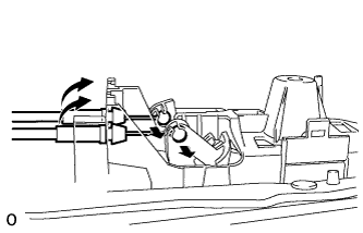
Remove the rear door glass inner weatherstrip LH by pulling it upward in the direction indicated by the arrow.
-
-
for Standard Body:
-
Remove the rear door glass inner weatherstrip LH by pulling it upward in the direction indicated by the arrow.
-
-
-
REMOVE REAR NO. 1 SPEAKER ASSEMBLY
Note
Do not touch the cone of the speaker.
-
Disconnect the connector.
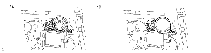
Text in Illustration *A for Standard *B for 19 Speakers -
Remove the 2 screws.
-
Detach the clip and remove the rear No. 1 speaker assembly.
-
-
REMOVE REAR DOOR SPEAKER COVER
-
Remove the 3 screws.
-
Disconnect the claw and remove the rear door speaker cover.
-
-
REMOVE REAR NO. 2 SPEAKER ASSEMBLY (for 19 Speakers)
Note
Do not touch the cone of the speaker.
-
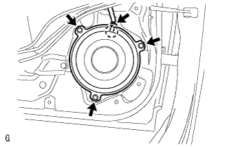
Disconnect the connector.
-
Remove the 3 screws.
-
Detach the claw and remove the rear No. 2 speaker assembly.
-
-
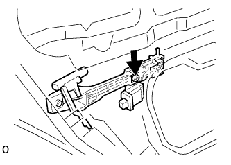
REMOVE REAR DOOR ECU LH
-
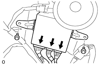
Remove the 2 screws and rear door ECU LH.
-
Disconnect the 3 connectors.
-
-
REMOVE REAR DOOR SERVICE HOLE COVER LH
-
Remove the rear door service hole cover LH.
-
-
REMOVE REAR DOOR DIVISION BAR LOWER BRACKET LH
-
Remove the 3 nuts and rear door division bar lower bracket LH.
-
-
REMOVE REAR DOOR WINDOW DIVISION BAR SUB-ASSEMBLY LH
-
Remove the 2 nuts.
-
Remove the rear door window division bar sub-assembly LH together with the rear door glass run LH.
-
-
REMOVE REAR DOOR GLASS RUN LH
-
Remove the rear door glass run LH from the division bar assembly.
-
-
REMOVE REAR DOOR QUARTER WINDOW GLASS LH
-
Remove the rear door quarter window glass LH and rear door quarter window weatherstrip LH as a unit as shown in the illustration.
-
-
REMOVE REAR DOOR GLASS SUB-ASSEMBLY LH
-
Remove the hole plug.
-
Remove the 2 bolts.
Note
Be careful when removing the bolts as the glass may fall and become damaged.
-
Remove the rear door glass sub-assembly LH.
Tech Tips
Remove the glass upward.
Note
Be careful not to damage the glass.
-
-
REMOVE REAR DOOR UPPER WINDOW FRAME MOULDING LH
-
for Standard Body:
-
for Long Body:
-
-
REMOVE REAR DOOR BELT MOULDING LH
-
Remove the 2 screws.
-
Loosen the 5 belt line screws indicated by the arrows in the illustration.
-
Remove the 3 screws.
-
Put protective tape around the rear door belt moulding LH.
-
While making sure not to pull the rear door belt moulding LH away from the vehicle, rotate the rear door belt moulding LH in the direction shown in the illustration and remove it.
Note
Be careful not to damage the door panel when rotating the belt moulding.
Tech Tips
The clip will break when the rear belt moulding is removed.
-
Remove the remaining part of the clip from the body.
Text in Illustration *1 Protective Tape
-
-
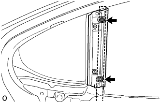
REMOVE REAR DOOR FRONT WINDOW GUIDE SUB-ASSEMBLY LH
-
Remove the 2 bolts and rear door front window guide sub-assembly LH.
-
-
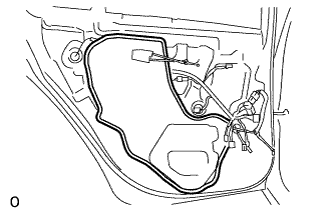
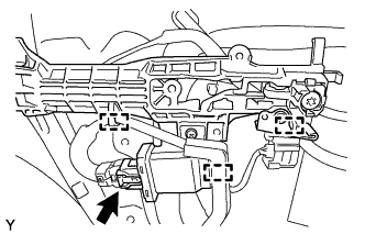
REMOVE REAR DOOR WINDOW REGULATOR SUB-ASSEMBLY LH
-
Disconnect the connector.
-
Text in Illustration *1 Temporary Bolt Loosen the temporary bolt.
Note
Do not remove the temporary bolt. If the temporary bolt is removed, the window regulator may fall and become damaged.
-
Remove the 3 bolts and rear door window regulator sub-assembly LH.
Note
Be careful when removing the screws as the motor may fall and become damaged.
-
Remove the temporary bolt from the rear door window regulator sub-assembly LH.
-
-
REMOVE POWER WINDOW REGULATOR MOTOR ASSEMBLY LH
-
Using a T25 ''TORX'' driver, remove the 3 screws and power window regulator motor assembly LH.
Note
Be careful when removing the screws as the motor may fall and become damaged.
-
-
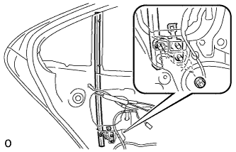
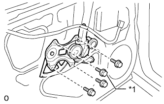
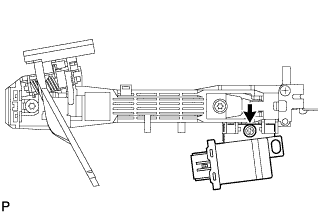
REMOVE REAR DOOR LOCK ASSEMBLY LH
-
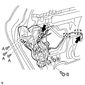
Disconnect the 2 connectors and detach the 2 clamps.
-
Using a T30 'TORX' socket, remove the 3 screws labeled A and 2 screws labeled B.
-
Remove the rear door lock assembly LH.
Note
Be careful when removing the bolts as the door lock may fall and become damaged.
Tech Tips
Remove the door lock through the service hole.
-
-
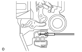
REMOVE REAR DOOR LOCK REMOTE CONTROL CABLE ASSEMBLY LH
-
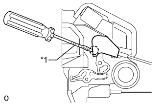
Text in Illustration *1 Protective Tape Using a screwdriver, detach the claw.
Tech Tips
Tape the screwdriver tip before use.
-
Remove the rear door lock remote control cable assembly LH.
-
-
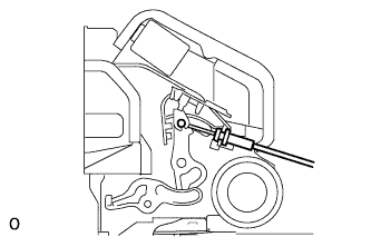
REMOVE REAR DOOR INSIDE LOCKING CABLE ASSEMBLY LH
-
Using a screwdriver, detach the 3 claws.
Tech Tips
Tape the screwdriver tip before use.
Text in Illustration *1 Protective Tape -
Remove the rear door inside locking cable assembly LH.
-
-
REMOVE REAR DOOR OUTSIDE HANDLE COVER LH
-
Using a T30 ''TORX'' socket, loosen the screw and remove the rear door outside handle cover LH.
-
-
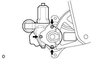
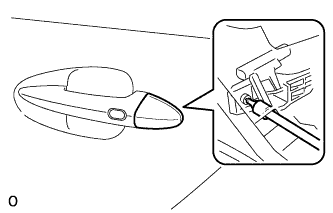
REMOVE REAR DOOR OUTSIDE HANDLE ASSEMBLY LH
-
Using a T30 "TORX" wrench, loosen the screw.
-
Disconnect the connector.
-
Remove the rear door outside handle assembly LH by sliding and pulling it in the direction indicated by the arrow in the illustration.
-
-
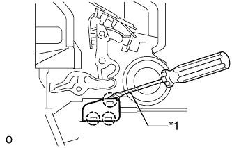
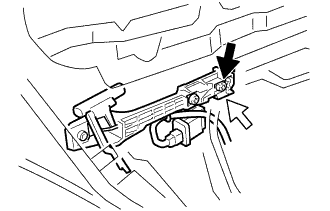
REMOVE REAR DOOR OUTSIDE HANDLE FRAME SUB-ASSEMBLY LH
-
Using a T30 ''TORX'' socket, remove the screw and rear door outside handle frame sub-assembly LH.
Tech Tips
Remove the outside handle frame through the service hole.
-
Disconnect the connector and detach the 3 clamps.
-
-
REMOVE DOOR ELECTRICAL KEY OSCILLATOR (for Rear Door)
-
Remove the screw and door electrical key oscillator.
-
-
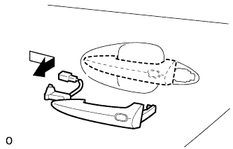
REMOVE REAR DOOR FRONT OUTSIDE HANDLE PAD
-
Detach the 3 claws and remove the rear door front outside handle pad.
-
-
REMOVE REAR DOOR REAR OUTSIDE HANDLE PAD
-
Detach the 2 claws and remove the rear door rear outside handle pad.
-
-
REMOVE REAR DOOR CHECK COVER LH
-
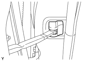
Remove the rear door check cover LH.
-
-
REMOVE REAR DOOR CHECK ASSEMBLY LH
-
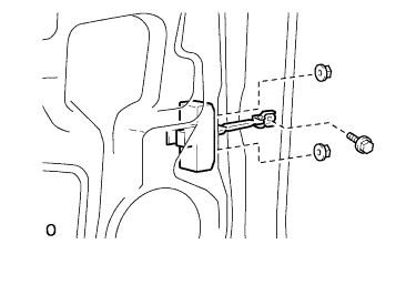
Remove the bolt, 2 nuts and rear door check assembly LH.
Tech Tips
Remove the door check through the service hole.
Note
Be careful when removing the bolts as the door check may fall and become damaged.
-
-
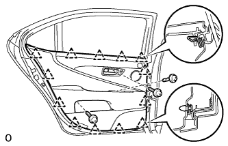
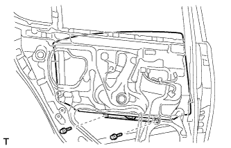
REMOVE REAR DOOR WEATHERSTRIP LH
-
for Long Body:
-
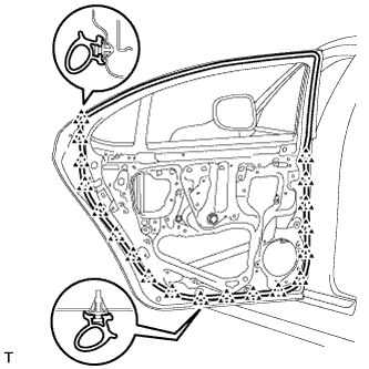
Detach the 19 clips and remove the rear door weatherstrip LH.
-
-
for Standard Body:
-
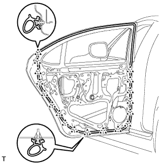
Detach the 18 clips and remove the rear door weatherstrip LH.
-
-