FUEL LID OPENER SYSTEM Fuel Lid Opener does not Operate
DESCRIPTION
-
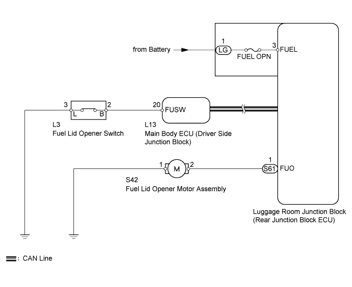
When the fuel lid opener switch is pushed, a fuel lid opener switch signal is sent to the main body ECU (driver side junction block) to the rear junction block ECU via the CAN line. If the main body ECU (driver side junction block) is not sounding the alarm or is not in the warning state, the main body ECU (driver side junction block) sends a fuel lid open output request signal to the rear junction block ECU via the CAN line, and operates the fuel lid opener motor assembly.
WIRING DIAGRAM
INSPECTION PROCEDURE
PROCEDURE
-
CHECK CAN COMMUNICATION SYSTEM
-
Check for DTC.
-
for LHD : Click here
-
for RHD : Click here
Result Result Proceed to CAN communication system DTC is not output A CAN communication system DTC (for LHD) is output B CAN communication system DTC (for RHD) is output C -
B 
Go to CAN COMMUNICATION SYSTEM Click here
C
Go to CAN COMMUNICATION SYSTEM Click here
A 
-
-
INSPECT FUSE (FUEL OPN)
-
Remove the FUEL OPN fuse from the luggage room junction block ECU.
-
Measure the resistance according to the value(s) in the table below.
Standard resistance Tester Connection Condition Specified Condition FUEL OPN fuse Always Below 1 Ω
NG
REPLACE FUSE
OK
-
-
PERFORM ACTIVE TEST USING INTELLIGENT TESTER (FUEL LID OPENER MOTOR)
-
Select the ACTIVE TEST, use the intelligent tester to generate a control command, and then check that the fuel lid opener motor assembly operates normally.
Body No.4 Tester Display Test Part Control Range Diagnostic Note Fuel Lid Open Operate fuel lid opener motor assembly) ON / OFF - OK Fuel filler door is opened by "ACTIVE TEST".
NG 
INSPECT FUEL LID OPENER MOTOR ASSEMBLY Click here
OK
-
-
READ VALUE USING DATA LIST (FUEL LID OPENER SWITCH)
-
Use the DATA LIST to check if the switch is functioning properly.
Main Body Tester Display Measurement Item/Range Normal Condition Diagnostic Note Fuel Lid Opener Switch Fuel lid opener switch signal/ON or OFF ON: Fuel lid opener switch is pushed
OFF: Fuel lid opener switch is not pushed
- OK When the switch is operating, intelligent tester should display as shown in the chart.
NG
CHECK HARNESS AND CONNECTOR (FUEL LID OPENER SWITCH - MAIN BODY ECU AND BODY GROUND) Click here
OK 
REPLACE MAIN BODY ECU (DRIVER SIDE JUNCTION BLOCK)
-
-
CHECK HARNESS AND CONNECTOR (FUEL LID OPENER SWITCH - MAIN BODY ECU AND BODY GROUND)
-
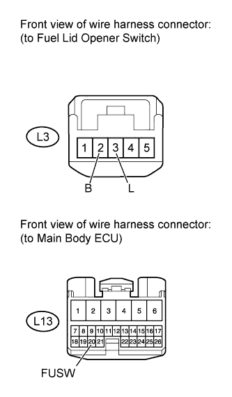
Disconnect the L3 switch connector.
-
Disconnect the L13 ECU connector.
-
Measure the resistance according to the value(s) in the table below.
Standard resistance Tester Connection Condition Specified Condition L3-2 (B) - L13-20 (FUSW) Always Below 1 Ω L3-3 (L) - Body ground L13-20 (FUSW) - Body ground Always 10 kΩ or higher
NG
REPAIR OR REPLACE HARNESS OR CONNECTOR
OK
REPLACE LUGGAGE DOOR OPENING SWITCH ASSEMBLY (FUEL LID OPENER SWITCH) Click here
-
-
INSPECT FUEL LID OPENER MOTOR ASSEMBLY
-
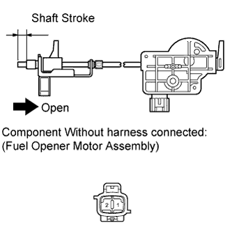
Apply battery voltage to the lock and check the operation of the lock.
OK Measurement Condition Specified Condition Battery positive (+) → Terminal 2
Battery negative (-) → Terminal 1
Shaft moves to open direction -
Check the shaft stroke.
Shaft stroke 10.6 mm (0.406 in.) or more
NG
REPLACE FUEL LID OPENER MOTOR ASSEMBLY Click here
OK
-
-
CHECK HARNESS AND CONNECTOR (FUEL LID OPENER MOTOR - REAR JUNCTION BLOCK ECU AND BODY GROUND)
-
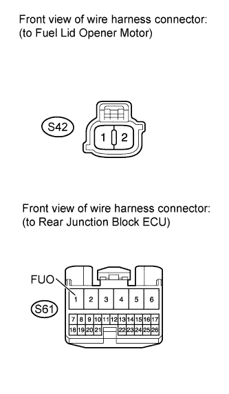
Disconnect the S42 motor connector.
-
Disconnect the S61 ECU connector.
-
Measure the resistance according to the value(s) in the table below.
Standard resistance Tester Connection Condition Specified Condition S42-2 - S61-1 (FUO) Always Below 1 Ω S42-1 - Body ground S61-1 (FUO) - Body ground Always 10 kΩ or higher
NG
REPAIR OR REPLACE HARNESS OR CONNECTOR
OK
REPLACE LUGGAGE ROOM JUNCTION BLOCK ASSEMBLY
-