DESCRIPTION
The position control ECU operates the lumbar motor based on the signals received from the seat vibrator switch to adjust the seat vibrator position.
INSPECTION PROCEDURE
PROCEDURE
- Click here
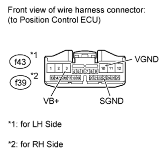
CHECK HARNESS AND CONNECTOR (POSITION CONTROL ECU - BATTERY AND BODY GROUND)
-
for LH Side:
Disconnect the f43 ECU connector.
-
for RH Side:
Disconnect the f39 ECU connector.
-
Measure the voltage according to the value(s) in the table below.
Standard voltage Table 1. for LH Side Tester Connection Condition Specified Condition f43-3 (VB+) - Body ground Always 11 to 14 V Table 2. for RH Side Tester Connection Condition Specified Condition f39-3 (VB+) - Body ground Always 11 to 14 V -
Measure the resistance according to the value(s) in the table below.
Standard resistance Table 3. for LH Side Tester Connection Condition Specified Condition f43-10 (VGND) - Body ground Always Below 1 Ω f43-23 (SGND) - Body ground Always Below 1 Ω Table 4. for RH Side Tester Connection Condition Specified Condition f39-10 (VGND) - Body ground Always Below 1 Ω f39-23 (SGND) - Body ground Always Below 1 Ω
- OKClick here
- NGClick here
-
- Click here
CHECK POSITION CONTROL ECU (SWITCH CIRCUIT)
-
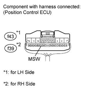
Remove the position control ECU with its connectors still connected
-
Measure the voltage according to the value(s) in the table below.
Standard voltage Table 5. for LH Side Tester Connection Switch Condition Specified Condition f43-21 (MSW) - Body ground Power switch on (IG)
Lumbar switch (rearward) ON
Below 1 V Power switch on (IG)
Lumbar switch (forward) ON
2 to 3 V Other than above 4 to 5 V Table 6. for RH Side Tester Connection Switch Condition Specified Condition f39-21 (MSW) - Body ground Power switch on (IG)
Lumbar switch (rearward) ON
Below 1 V Power switch on (IG)
Lumbar switch (forward) ON
2 to 3 V Other than above 4 to 5 V
- OKClick here
- NGClick here
-
- Click here
INSPECT SEPARATE TYPE REAR SEATBACK ASSEMBLY (LUMBAR MOTOR)
-
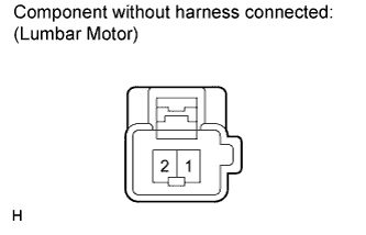
Check the operation of the lumbar motor.
-
Apply battery voltage to the lumbar motor.
-
Check that the lumbar support adjuster moves smoothly.
OK Table 7. for LH Side Measurement Condition Operation Direction Battery positive (+) → 2
Battery negative (-) → 1
Forward Battery positive (+) → 1
Battery negative (-) → 2
Backward Table 8. for RH Side Measurement Condition Operation Direction Battery positive (+) → 1
Battery negative (-) → 2
Forward Battery positive (+) → 2
Battery negative (-) → 1
Backward Table 9. Result Result Proceed to OK A NG (w/o Ottoman) B NG (w/ Ottoman) C
-
-
- Click here
CHECK HARNESS AND CONNECTOR (POSITION CONTROL ECU - LUMBAR MOTOR)
-
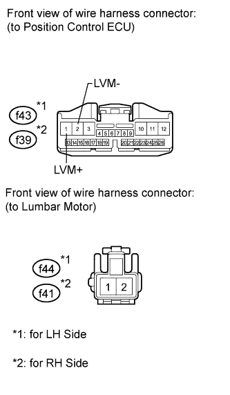
for LH Side:
-
Disconnect the f43 ECU connector.
-
Disconnect the f44 motor connector.
-
-
for RH Side:
-
Disconnect the f39 ECU connector.
-
Disconnect the f41 motor connector.
-
-
Measure the resistance according to the value(s) in the table below.
Standard resistance Table 10. for LH Side Tester Connection Condition Specified Condition f43-1 (LVM+) - f44-2 Always Below 1 Ω f43-2 (LVM-) - f44-1 Always Below 1 Ω f43-1 (LVM+) - Body ground Always 10 kΩ or higher f43-2 (LVM-) - Body ground Always 10 kΩ or higher Table 11. for RH Side Tester Connection Condition Specified Condition f39-1 (LVM+) - f41-1 Always Below 1 Ω f39-2 (LVM-) - f41-2 Always Below 1 Ω f39-1 (LVM+) - Body ground Always 10 kΩ or higher f39-2 (LVM-) - Body ground Always 10 kΩ or higher Table 12. Result Result Proceed to OK (w/ Ottoman) A OK (w/o Ottoman) B NG C
-
- Click here
CHECK SEAT TYPE
-
Check seat type.
Table 13. Result Result Proceed to for 4-Passenger with Ottoman A for 5-Passenger with Ottoman B
-
- Click here
CHECK HARNESS AND CONNECTOR (POSITION CONTROL ECU - SEAT VIBRATOR SWITCH AND BODY GROUND)
-
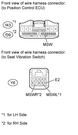
for LH Side:
Disconnect the f43 ECU connector.
-
Disconnect the Y6 switch connector.
-
for RH Side:
Disconnect the f39 ECU connector.
-
Disconnect the Y6 switch connector.
-
Measure the resistance according to the value(s) in the table below.
Standard resistance Table 14. for LH Side Tester Connection Condition Specified Condition f43-21 (MSW) - Y6-9 (MSWL) Always Below 1 Ω Y6-10 (E2) - Body ground Always Below 1 Ω f43-21 (MSW) - Body ground Always 10 kΩ or higher Table 15. for RH Side Tester Connection Condition Specified Condition f39-21 (MSW) - Y6-7 (MSWR) Always Below 1 Ω Y6-10 (E2) - Body ground Always Below 1 Ω f39-21 (MSW) - Body ground Always 10 kΩ or higher
- OKClick here
- NGClick here
-
- Click here
CHECK SEAT VIBRATOR SWITCH (OPERATION)
-
Replace the seat vibrator switch with a new or normally operating one. Perform an operation inspection.
OK Lumbar motor operates normally.
- OKClick here
- NGClick here
-
- Click here
END (SEAT VIBRATOR SWITCH IS DEFECTIVE)
- Click here
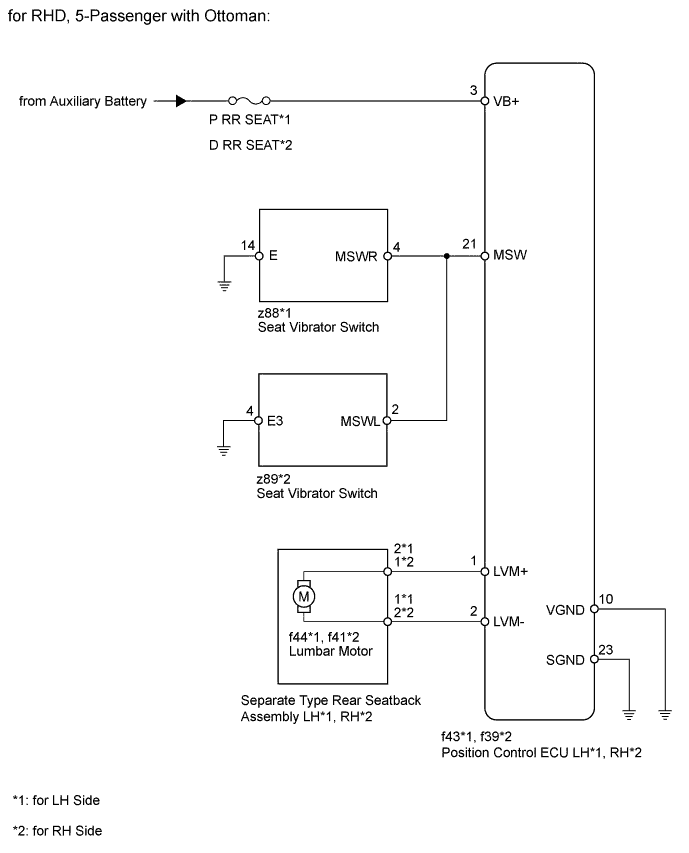
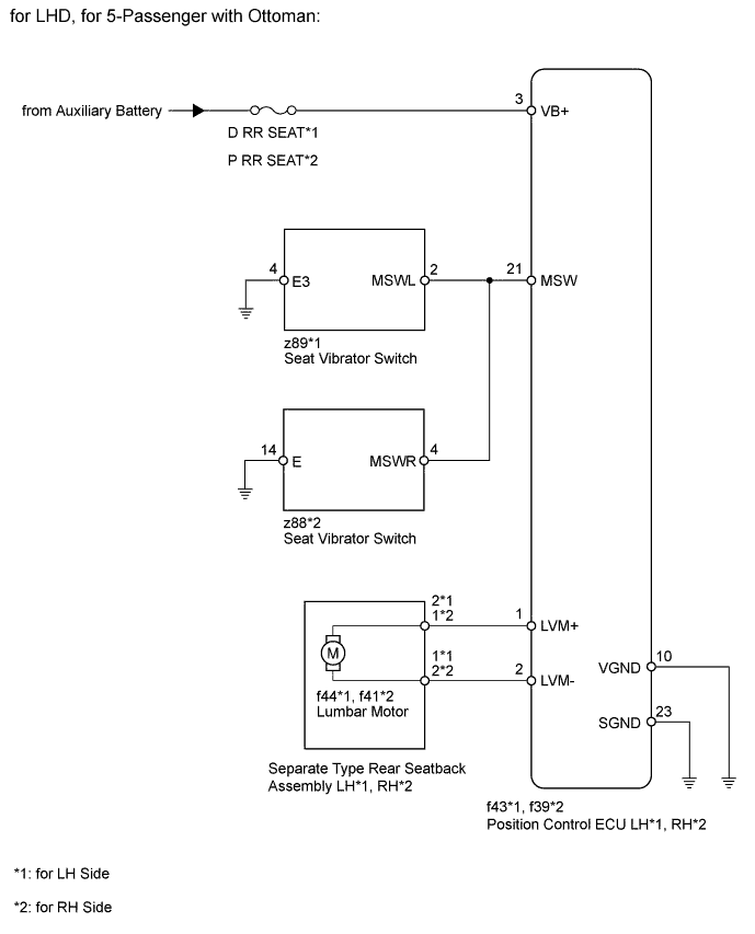
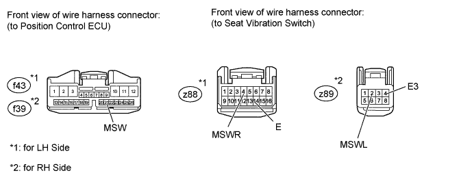
CHECK HARNESS AND CONNECTOR (POSITION CONTROL ECU - SEAT VIBRATOR SWITCH AND BODY GROUND)
Tip:*1: LH Side
*2: RH Side
-
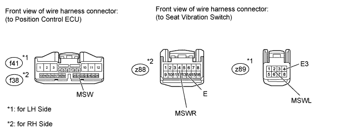
for LHD:
-
Disconnect the f43*1 or f39*2 ECU connector.
-
Disconnect the z88*1 or z89*2 switch connector.
-
-
for RHD:
-
Disconnect the f43*1 or f39*2 ECU connector.
-
Disconnect the z89*1 or z88*2 switch connector.
-
-
Measure the resistance according to the value(s) in the table below.
Standard resistance Table 16. for LHD Tester Connection Condition Specified Condition f43-21 (MSW) - z89-2 (MSWLR)*1 Always Below 1 Ω z89-4 (E3) - Body ground*1 Always Below 1 Ω f43-21 (MSW) - Body ground*1 Always 10 kΩ or higher f39-21 (MSW) - z88-4 (MSWR)*2 Always Below 1 Ω z88-14 (E) - Body ground*2 Always Below 1 Ω f39-21 (MSW) - Body ground*2 Always 10 kΩ or higher Table 17. for RHD Tester Connection Condition Specified Condition f43-21 (MSW) - z88-4 (MSWR)*1 Always Below 1 Ω z88-14 (E) - Body ground*1 Always Below 1 Ω f43-21 (MSW) - Body ground*1 Always 10 kΩ or higher f39-21 (MSW) - z89-2 (MSWL)*2 Always Below 1 Ω z89-4 (E3) - Body ground*2 Always Below 1 Ω f39-21 (MSW) - Body ground*2 Always 10 kΩ or higher
- OKClick here
- NGClick here
-
- Click here
CHECK SEAT VIBRATOR SWITCH (OPERATION)
-
Replace the seat vibrator switch with a new or normally operating one. Perform an operation inspection.
OK Lumbar motor operates normally.
- OKClick here
- NGClick here
-
- Click here
END (SEAT VIBRATOR SWITCH IS DEFECTIVE)
- Click here
REPAIR OR REPLACE HARNESS OR CONNECTOR
- Click here
REPLACE SEPARATE TYPE REAR SEATBACK ASSEMBLYClick here
- Click here
REPLACE SEPARATE TYPE REAR SEATBACK ASSEMBLYClick here
- Click here
REPLACE POSITION CONTROL ECUClick here
- Click here
REPAIR OR REPLACE HARNESS OR CONNECTOR
- Click here
REPAIR OR REPLACE HARNESS OR CONNECTOR
- Click here
REPLACE POSITION CONTROL ECUClick here
- Click here
REPAIR OR REPLACE HARNESS OR CONNECTOR
- Click here
REPLACE POSITION CONTROL ECUClick here