REAR POWER SEAT CONTROL SYSTEM, Diagnostic DTC:B2650

| DTC Code | DTC Name |
|---|---|
| B2650 | Slide Sensor Malfunction |
DESCRIPTION
When the position control ECU does not receive a sensor signal despite forward or backward movement of seat by power seat motor operation, this DTC is output.
| DTC Code | DTC Detection Condition | Trouble Area |
|---|---|---|
| B2650 | Sensor's forward and backward lock detection position is the same |
|
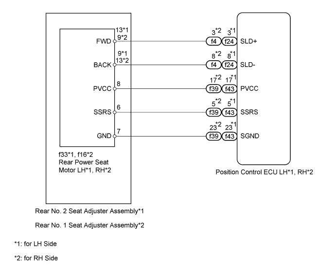
WIRING DIAGRAM
INSPECTION PROCEDURE
PROCEDURE
-
CHECK FOR DTC
-
DTC output area check
-
Using the intelligent tester, determine the area that output the DTC.
Result Result Proceed to B2650 output from rear left seat ECU A B2650 output from rear right seat ECU B
-
B 
PERFORM ACTIVE TEST USING INTELLIGENT TESTER (POWER SEAT MOTOR FUNCTION) Click here
A 
-
-
PERFORM ACTIVE TEST USING INTELLIGENT TESTER (POWER SEAT MOTOR FUNCTION)
-
Select the Active Test, use the intelligent tester to generate a control command, and then check the power seat motor function.
Rear Left Seat Tester Display Test Part Control Range Diagnostic Note Seat Slide Operation Seat sliding operation Front / OFF / Rear - OK Motor operates normally.
NG
INSPECT REAR NO. 2 SEAT ADJUSTER ASSEMBLY (POWER SEAT MOTOR) Click here
OK
-
-
CHECK HARNESS AND CONNECTOR (POSITION CONTROL ECU LH - REAR POWER SEAT MOTOR LH)
-
Disconnect the f43 ECU connector.
-
Disconnect the f33 motor connector.
-
Measure the resistance according to the value(s) in the table below.
Standard resistance Tester Connection Condition Specified Condition f43-17 (PVCC) - f33-8 (PVCC) Always Below 1 Ω f43-5 (SSRS) - f33-6 (SSRS) Always Below 1 Ω f43-23 (SGND) - f33-7 (GND) Always Below 1 Ω f43-17 (PVCC) - Body ground Always 10 kΩ or higher f43-5 (SSRS) - Body ground Always 10 kΩ or higher f43-23 (SGND) - Body ground Always 10 kΩ or higher
NG 
REPAIR OR REPLACE HARNESS OR CONNECTOR
OK
-
-
CHECK REAR NO. 2 SEAT ADJUSTER ASSEMBLY (POSITION CONTROL SENSOR)
-
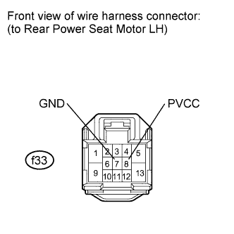
Disconnect the f33 motor connector.
-
Measure the voltage according to the value(s) in the table below.
Standard voltage Tester Connection Switch Condition Specified Condition f33-8 (PVCC) - f33-7 (GND) Slide switch ON 7.2 to 8.8 V Result Result Proceed to OK A NG (except Ottoman) B NG (for Ottoman) C
B
REPLACE POSITION CONTROL ECU LH Click here
C
REPLACE POSITION CONTROL ECU LH Click here
A
-
-
CHECK REAR NO. 2 SEAT ADJUSTER ASSEMBLY (POSITION CONTROL SENSOR)
-
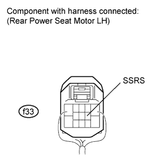
Reconnect the f33 motor connector.
-
Measure the voltage according to the value(s) in the table below.
Standard voltage Tester Connection Switch Condition Specified Condition f33-6 (SSRS) - Body ground Slide switch ON 0 to 8 V Result Result Proceed to OK A NG (except Ottoman) B NG (for Ottoman) C
B
REPLACE REAR NO. 2 SEAT ADJUSTER ASSEMBLY Click here
C
REPLACE REAR NO. 2 SEAT ADJUSTER ASSEMBLY Click here
A
-
-
CHECK FOR DTC
-
Clear the DTC Click here.
-
Recheck for DTC.
OK DTC B2650 is not output. Result Result Proceed to OK A NG (except Ottoman) B NG (for Ottoman) C
B
REPLACE POSITION CONTROL ECU LH Click here
C
REPLACE POSITION CONTROL ECU LH Click here
A 
USE SIMULATION METHOD TO CHECK Click here
-
-
INSPECT REAR NO. 2 SEAT ADJUSTER ASSEMBLY (POWER SEAT MOTOR)
-
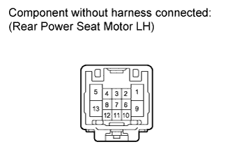
Check operation of the power seat motor (slide motor).
-
Check if the seat adjuster moves smoothly when the battery is connected to the slide motor connector terminals.
OK Measurement Condition Operational Direction Battery positive (+) → 13
Battery negative (-) → 9
Forward Battery positive (+) → 9
Battery negative (-) → 13
Backward Result Result Proceed to OK A NG (except Ottoman) B NG (for Ottoman) C
-
B
REPLACE REAR NO. 2 SEAT ADJUSTER ASSEMBLY Click here
C
REPLACE REAR NO. 2 SEAT ADJUSTER ASSEMBLY Click here
A
-
-
CHECK HARNESS AND CONNECTOR (POSITION CONTROL ECU LH - REAR POWER SEAT MOTOR LH)
-
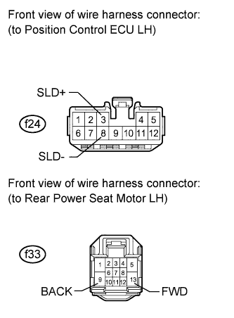
Disconnect the f24 ECU connector.
-
Disconnect the f33 motor connector.
-
Measure the resistance according to the value(s) in the table below.
Standard resistance Tester Connection Condition Specified Condition f24-3 (SLD+) - f33-13 (FWD) Always Below 1 Ω f24-8 (SLD-) - f33-9 (BACK) Always Below 1 Ω Result Result Proceed to OK (except Ottoman) A OK (for Ottoman) B NG C
B
REPLACE POSITION CONTROL ECU LH Click here
C
REPAIR OR REPLACE HARNESS OR CONNECTOR
A
REPLACE POSITION CONTROL ECU LH Click here
-
-
PERFORM ACTIVE TEST USING INTELLIGENT TESTER (POWER SEAT MOTOR FUNCTION)
-
Select the Active Test, use the intelligent tester to generate a control command, and then check the power seat motor function.
Rear Right Seat Tester Display Test Part Control Range Diagnostic Note Seat Slide Operation Seat sliding operation Front / OFF / Rear - OK Motor operates normally.
NG
INSPECT REAR NO. 1 SEAT ADJUSTER ASSEMBLY (POWER SEAT MOTOR) Click here
OK
-
-
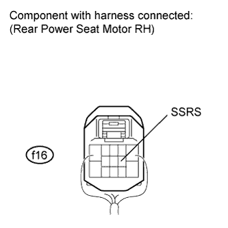
CHECK HARNESS AND CONNECTOR (POSITION CONTROL ECU RH - REAR POWER SEAT MOTOR RH)
-
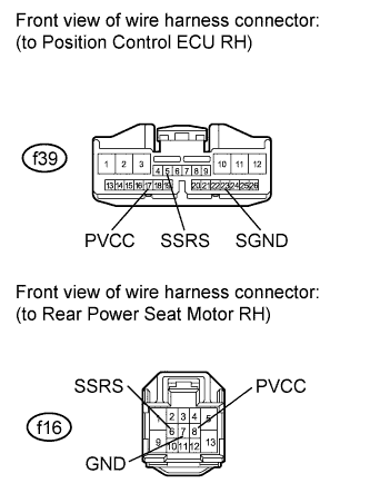
Disconnect the f39 ECU connector.
-
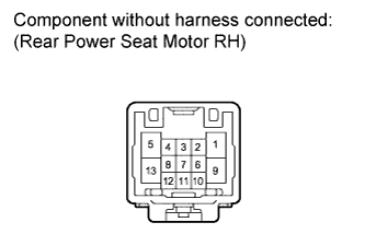
Disconnect the f16 motor connector.
-
Measure the resistance according to the value(s) in the table below.
Standard resistance Tester Connection Condition Specified Condition f39-17 (PVCC) - f16-8 (PVCC) Always Below 1 Ω f39-5 (SSRS) - f16-6 (SSRS) Always Below 1 Ω f39-23 (SGND) - f16-7 (GND) Always Below 1 Ω f39-17 (PVCC) - Body ground Always 10 kΩ or higher f39-5 (SSRS) - Body ground Always 10 kΩ or higher f39-23 (SGND) - Body ground Always 10 kΩ or higher
NG
REPAIR OR REPLACE HARNESS OR CONNECTOR
OK
-
-
CHECK REAR NO. 1 SEAT ADJUSTER ASSEMBLY (POSITION CONTROL SENSOR)
-
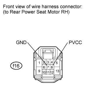
Disconnect the f16 motor connector.
-
Measure the voltage according to the value(s) in the table below.
Standard voltage Tester Connection Switch Condition Specified Condition f16-8 (PVCC) - f16-7 (GND) Slide switch ON 7.2 to 8.8 V Result Result Proceed to OK A NG (except Ottoman) B NG (for Ottoman) C
B
REPLACE POSITION CONTROL ECU RH Click here
C
REPLACE POSITION CONTROL ECU RH Click here
A
-
-
CHECK REAR NO. 1 SEAT ADJUSTER ASSEMBLY (POSITION CONTROL SENSOR)
-
Reconnect the f16 motor connector.
-
Measure the voltage according to the value(s) in the table below.
Standard voltage Tester Connection Switch Condition Specified Condition f16-6 (SSRS) - Body ground Slide switch ON 0 to 8 V Result Result Proceed to OK A NG (except Ottoman) B NG (for Ottoman) C
B
REPLACE REAR NO. 1 SEAT ADJUSTER ASSEMBLY Click here
C
REPLACE REAR NO. 1 SEAT ADJUSTER ASSEMBLY Click here
A
-
-
CHECK FOR DTC
-
Clear the DTC Click here.
-
Recheck for DTC.
OK DTC B2650 is not output. Result Result Proceed to OK A NG (except Ottoman) B NG (for Ottoman) C
B
REPLACE POSITION CONTROL ECU RH Click here
C
REPLACE POSITION CONTROL ECU RH Click here
A
USE SIMULATION METHOD TO CHECK Click here
-
-
INSPECT REAR NO. 1 SEAT ADJUSTER ASSEMBLY (POWER SEAT MOTOR)
-
Check operation of the power seat motor (slide motor).
-
Check if the seat adjuster moves smoothly when the battery is connected to the slide motor connector terminals.
OK Measurement Condition Operational Direction Battery positive (+) → 9
Battery negative (-) → 13
Forward Battery positive (+) → 13
Battery negative (-) → 9
Backward Result Result Proceed to OK A NG (except Ottoman) B NG (for Ottoman) C
-
B
REPLACE REAR NO. 1 SEAT ADJUSTER ASSEMBLY Click here
C
REPLACE REAR NO. 1 SEAT ADJUSTER ASSEMBLY Click here
A
-
-
CHECK HARNESS AND CONNECTOR (POSITION CONTROL ECU RH - REAR POWER SEAT MOTOR RH)
-
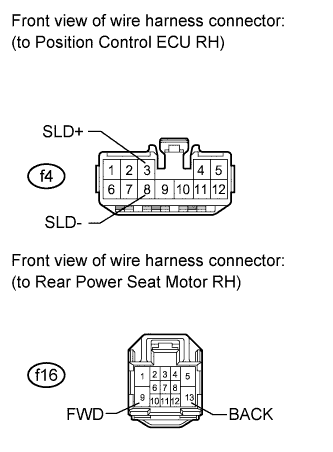
Disconnect the f4 ECU connector.
-
Disconnect the f16 motor connector.
-
Measure the resistance according to the value(s) in the table below.
Standard resistance Tester Connection Condition Specified Condition f4-3 (SLD+) - f16-9 (FWD) Always Below 1 Ω f4-8 (SLD-) - f16-13 (BACK) Always Below 1 Ω Result Result Proceed to OK (except Ottoman) A OK (for Ottoman) B NG C
B
REPLACE POSITION CONTROL ECU RH Click here
C
REPAIR OR REPLACE HARNESS OR CONNECTOR
A
REPLACE POSITION CONTROL ECU RH Click here
-