FRONT POWER SEAT CONTROL SYSTEM, Diagnostic DTC:B2654

| DTC Code | DTC Name |
|---|---|
| B2654 | Headrest Sensor Malfunction |
DESCRIPTION
When the front power seat switch (seat ECU) does not receive a sensor signal despite forward or backward movement of seat by power seat motor operation, this DTC is output.
| DTC Code | DTC Detection Condition | Trouble Area |
|---|---|---|
| B2654 | Detected seat position does not change in response to seat movement |
|
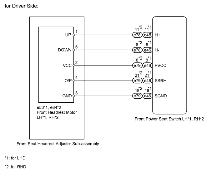
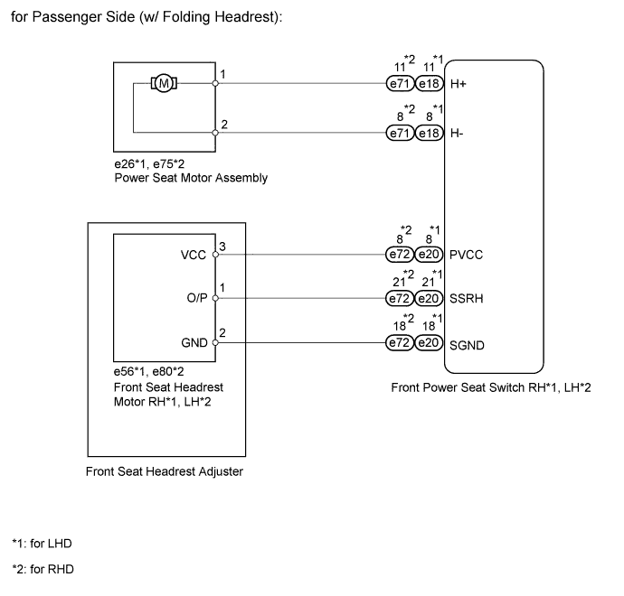
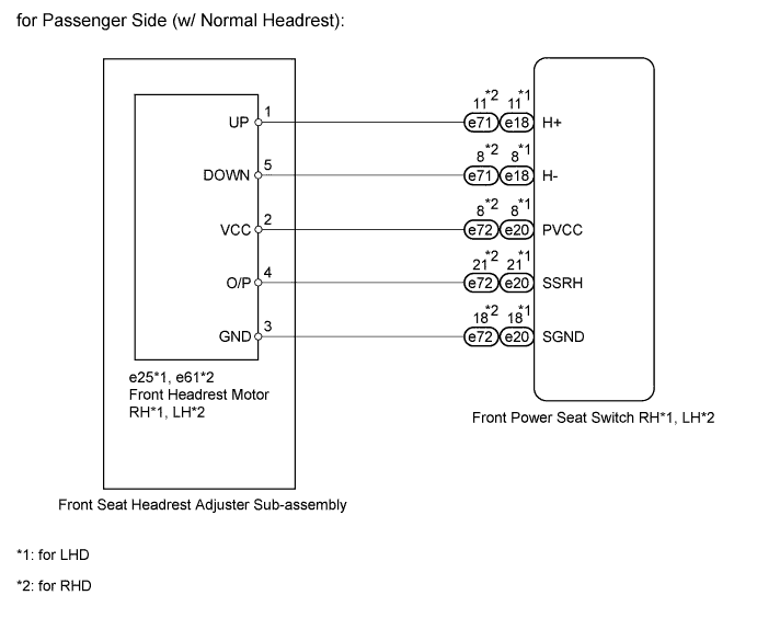
WIRING DIAGRAM
INSPECTION PROCEDURE
PROCEDURE
-
CHECK FOR DTC
-
DTC output area check
-
Using the intelligent tester, determine the area that output the DTC.
Result Result Proceed to B2654 output from driver seat ECU A B2654 output from passenger seat ECU B
-
B 
CHECK VEHICLE Click here
A 
-
-
PERFORM ACTIVE TEST USING INTELLIGENT TESTER (POWER SEAT MOTOR FUNCTION)
-
Select the Active Test, use the intelligent tester to generate a control command, and then check the power seat motor function.
Driver Seat Tester Display Test Part Control Range Diagnostic Note Headrest Operation Seat headrest operation UP / DOWN - OK Motor operates normally.
NG
CHECK FRONT SEAT HEADREST ADJUSTER SUB-ASSEMBLY (POWER SEAT MOTOR) Click here
OK
-
-
CHECK HARNESS AND CONNECTOR (FRONT POWER SEAT SWITCH - FRONT HEADREST MOTOR AND BODY GROUND)

-
for LHD:
-
Disconnect the e46 switch connector.
-
Disconnect the e53 motor connector.
-
-
for RHD:
-
Disconnect the e79 switch connector.
-
Disconnect the e84 motor connector.
-
-
Measure the resistance according to the value(s) in the table below.
Standard resistance for LHD Tester Connection Condition Specified Condition e46-8 (PVCC) - e53-2 (VCC) Always Below 1 Ω e46-21 (SSRH) - e53-4 (O/P) Always Below 1 Ω e46-18 (SGND) - e53-3 (GND) Always Below 1 Ω e46-8 (PVCC) - Body ground Always 10 kΩ or higher e46-21 (SSRH) - Body ground Always 10 kΩ or higher e46-18 (SGND) - Body ground Always 10 kΩ or higher for RHD Tester Connection Condition Specified Condition e79-8 (PVCC) - e84-2 (VCC) Always Below 1 Ω e79-21 (SSRH) - e84-4 (O/P) Always Below 1 Ω e79-18 (SGND) - e84-3 (GND) Always Below 1 Ω e79-8 (PVCC) - Body ground Always 10 kΩ or higher e79-21 (SSRH) - Body ground Always 10 kΩ or higher e79-18 (SGND) - Body ground Always 10 kΩ or higher
NG 
REPAIR OR REPLACE HARNESS OR CONNECTOR
OK
-
-
CHECK FRONT SEAT HEADREST ADJUSTER SUB-ASSEMBLY (POSITION CONTROL SENSOR)

-
for LHD:
Disconnect the e53 motor connector.
-
for RHD:
Disconnect the e84 motor connector.
-
Measure the voltage according to the value(s) in the table below.
Standard voltage for LHD Tester Connection Switch Condition Specified Condition e53-2 (VCC) - e53-3 (GND) Headrest switch signal ON 7.2 to 8.8 V for RHD Tester Connection Switch Condition Specified Condition e84-2 (VCC) - e84-3 (GND) Headrest switch signal ON 7.2 to 8.8 V
NG
REPLACE FRONT POWER SEAT SWITCH (for Driver Side) Click here
OK
-
-
CHECK FRONT SEAT HEADREST ADJUSTER SUB-ASSEMBLY (POSITION CONTROL SENSOR)
-
for LHD:
Reconnect the e53 motor connector.
-
for RHD:
Reconnect the e84 motor connector.
-
Measure the voltage according to the value(s) in the table below.
Standard voltage for LHD Tester Connection Switch Condition Specified Condition e53-4 (O/P) - Body ground Headrest switch signal ON 0 to 8 V for RHD Tester Connection Switch Condition Specified Condition e84-4 (O/P) - Body ground Headrest switch signal ON 0 to 8 V
NG
REPLACE FRONT SEAT HEADREST ADJUSTER SUB-ASSEMBLY Click here
OK
-
-
CHECK FOR DTC
-
Clear the DTC Click here.
-
Recheck the DTC.
OK DTC B2654 is not output.
NG
REPLACE FRONT POWER SEAT SWITCH (for Driver Side) Click here
OK 
END
-
-
CHECK FRONT SEAT HEADREST ADJUSTER SUB-ASSEMBLY (POWER SEAT MOTOR)
-
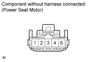
Check operation of the power seat motor (headrest motor).
-
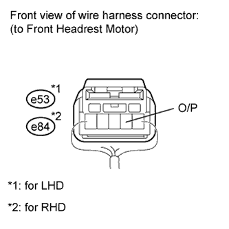
Check if the seat adjuster moves smoothly when the battery is connected to the headrest motor connector terminals.
OK Measurement Condition Operational Direction Battery positive (+) → 1
Battery negative (-) → 5
Upward Battery positive (+) → 5
Battery negative (-) → 1
Downward
-
NG
REPLACE FRONT SEAT HEADREST ADJUSTER SUB-ASSEMBLY Click here
OK
-
-
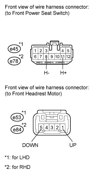
CHECK HARNESS AND CONNECTOR (FRONT POWER SEAT SWITCH - FRONT HEADREST MOTOR)
-
for LHD:
-
Disconnect the e45 switch connector.
-
Disconnect the e53 motor connector.
-
-
for RHD:
-
Disconnect the e78 switch connector.
-
Disconnect the e84 motor connector.
-
-
Measure the resistance according to the value(s) in the table below.
Standard resistance for LHD Tester Connection Condition Specified Condition e45-11 (H+) - e53-1 (UP) Always Below 1 Ω e45-8 (H-) - e53-5 (DOWN) Always Below 1 Ω e45-11 (H+) - Body ground Always 10 kΩ or higher e45-8 (H-) - Body ground Always 10 kΩ or higher for RHD Tester Connection Condition Specified Condition e78-11 (H+) - e84-1 (UP) Always Below 1 Ω e78-8 (H-) - e84-5 (DOWN) Always Below 1 Ω e78-11 (H+) - Body ground Always 10 kΩ or higher e78-8 (H-) - Body ground Always 10 kΩ or higher
NG
REPAIR OR REPLACE HARNESS OR CONNECTOR
OK
REPLACE FRONT POWER SEAT SWITCH (for Driver Side) Click here
-
-
CHECK VEHICLE
-
Check the type of headrest.
Result Result Proceed to w/ Folding Headrest A w/ Normal Headrest B
B
PERFORM ACTIVE TEST USING INTELLIGENT TESTER (POWER SEAT MOTOR FUNCTION) Click here
A
-
-
PERFORM ACTIVE TEST USING INTELLIGENT TESTER (POWER SEAT MOTOR FUNCTION)
-
Select the Active Test, use the intelligent tester to generate a control command, and then check the power seat motor function.
Passenger Seat Tester Display Test Part Control Range Diagnostic Note Headrest Operation Seat headrest operation UP / DOWN - OK Motor operates normally.
NG
CHECK POWER SEAT MOTOR ASSEMBLY Click here
OK
-
-
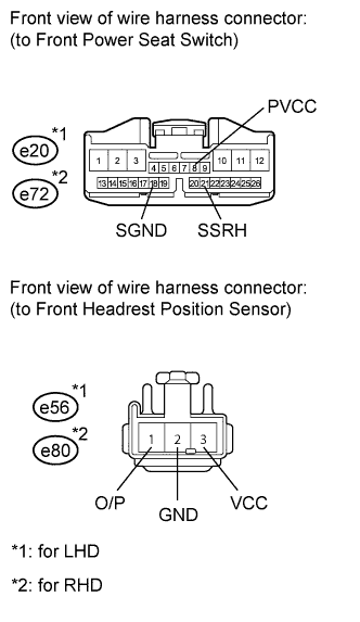
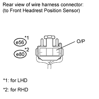
CHECK HARNESS AND CONNECTOR (FRONT POWER SEAT SWITCH - FRONT HEADREST POSITION SENSOR)
-
for LHD:
-
Disconnect the e20 switch connector.
-
Disconnect the e56 sensor connector.
-
-
for RHD:
-
Disconnect the e72 switch connector.
-
Disconnect the e80 sensor connector.
-
-
Measure the resistance according to the value(s) in the table below.
Standard resistance for LHD Tester Connection Condition Specified Condition e20-8 (PVCC) - e56-3 (VCC) Always Below 1 Ω e20-21 (SSRH) - e56-1 (O/P) Always Below 1 Ω e20-18 (SGND) - e56-2 (GND) Always Below 1 Ω e20-8 (PVCC) - Body ground Always 10 kΩ or higher e20-21 (SSRH) - Body ground Always 10 kΩ or higher e20-18 (SGND) - Body ground Always 10 kΩ or higher for RHD Tester Connection Condition Specified Condition e72-8 (PVCC) - e80-3 (VCC) Always Below 1 Ω e72-21 (SSRH) - e80-1 (O/P) Always Below 1 Ω e72-18 (SGND) - e80-2 (GND) Always Below 1 Ω e72-8 (PVCC) - Body ground Always 10 kΩ or higher e72-21 (SSRH) - Body ground Always 10 kΩ or higher e72-18 (SGND) - Body ground Always 10 kΩ or higher
NG
REPAIR OR REPLACE HARNESS OR CONNECTOR
OK
-
-
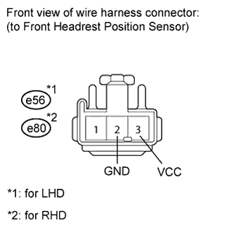
CHECK FRONT SEAT HEADREST ADJUSTER (POSITION CONTROL SENSOR)
-
for LHD:
Disconnect the e56 sensor connector.
-
for RHD:
Disconnect the e80 sensor connector.
-
Measure the voltage according to the value(s) in the table below.
Standard voltage for LHD Tester Connection Switch Condition Specified Condition e56-3 (VCC) - e56-2 (GND) Headrest switch signal ON 7.2 to 8.8 V for RHD Tester Connection Switch Condition Specified Condition e80-3 (VCC) - e80-2 (GND) Headrest switch signal ON 7.2 to 8.8 V
NG
REPLACE FRONT POWER SEAT SWITCH (for Passenger Side) Click here
OK
-
-
CHECK FRONT SEAT HEADREST ADJUSTER (POSITION CONTROL SENSOR)
-
for LHD:
Reconnect the e56 sensor connector.
-
for RHD:
Reconnect the e80 sensor connector.
-
Measure the voltage according to the value(s) in the table below.
Standard voltage for LHD Tester Connection Switch Condition Specified Condition e56-1 (O/P) - Body ground Headrest switch signal ON 0 to 8 V for RHD Tester Connection Switch Condition Specified Condition e80-1 (O/P) - Body ground Headrest switch signal ON 0 to 8 V
NG
REPLACE FRONT SEAT HEADREST ADJUSTER
OK
-
-
CHECK FOR DTC
-
Clear the DTC Click here.
-
Recheck the DTC.
OK DTC B2654 is not output.
NG
REPLACE FRONT POWER SEAT SWITCH (for Passenger Side) Click here
OK
END
-
-
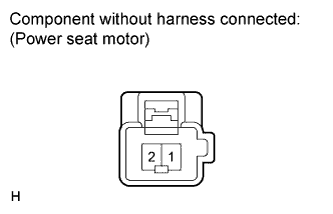
CHECK POWER SEAT MOTOR ASSEMBLY
-
Check operation of the power seat motor (headrest motor).
-
Check if the seat adjuster moves smoothly when the battery is connected to the headrest motor connector terminals.
OK Measurement Condition Operational Direction Battery positive (+) → 1
Battery negative (-) → 2
Upward Battery positive (+) → 2
Battery negative (-) → 1
Downward
-
NG
REPLACE POWER SEAT MOTOR ASSEMBLY
OK
-
-
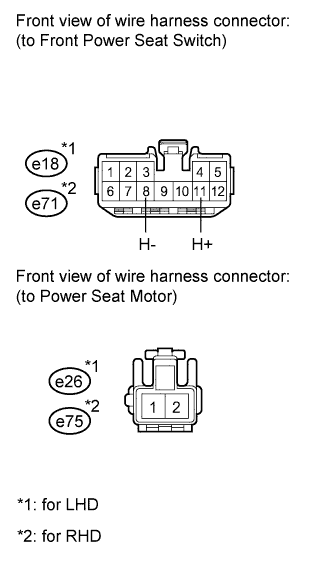
CHECK HARNESS AND CONNECTOR (FRONT POWER SEAT SWITCH - POWER SEAT MOTOR)
-
for LHD:
-
Disconnect the e18 switch connector.
-
Disconnect the e26 motor connector.
-
-
for RHD:
-
Disconnect the e71 switch connector.
-
Disconnect the e75 motor connector.
-
-
Measure the resistance according to the value(s) in the table below.
Standard resistance for LHD Tester Connection Condition Specified Condition e18-11 (H+) - e26-1 Always Below 1 Ω e18-8 (H-) - e26-2 Always Below 1 Ω e18-11 (H+) - Body ground Always 10 kΩ or higher e18-8 (H-) - Body ground Always 10 kΩ or higher for RHD Tester Connection Condition Specified Condition e71-11 (H+) - e75-1 Always Below 1 Ω e71-8 (H-) - e75-2 Always Below 1 Ω e71-11 (H+) - Body ground Always 10 kΩ or higher e71-8 (H-) - Body ground Always 10 kΩ or higher
NG
REPAIR OR REPLACE HARNESS OR CONNECTOR
OK
REPLACE FRONT SEAT HEADREST ADJUSTER SUB-ASSEMBLY Click here
-
-
PERFORM ACTIVE TEST USING INTELLIGENT TESTER (POWER SEAT MOTOR FUNCTION)
-
Select the Active Test, use the intelligent tester to generate a control command, and then check the power seat motor function.
Passenger Seat Tester Display Test Part Control Range Diagnostic Note Headrest Operation Seat headrest operation UP / DOWN - OK Motor operates normally.
NG
CHECK FRONT SEAT HEADREST ADJUSTER SUB-ASSEMBLY (POWER SEAT MOTOR) Click here
OK
-
-
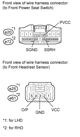
CHECK HARNESS AND CONNECTOR (FRONT POWER SEAT SWITCH - FRONT HEADREST MOTOR)
-
for LHD:
-
Disconnect the e20 switch connector.
-
Disconnect the e25 motor connector.
-
-
for RHD:
-
Disconnect the e72 switch connector.
-
Disconnect the e61 motor connector.
-
-
Measure the resistance according to the value(s) in the table below.
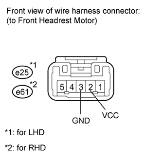
Standard resistance for LHD Tester Connection Condition Specified Condition e20-8 (PVCC) - e25-2 (VCC) Always Below 1 Ω e20-21 (SSRH) - e25-4 (O/P) Always Below 1 Ω e20-18 (SGND) - e25-3 (GND) Always Below 1 Ω e20-8 (PVCC) - Body ground Always 10 kΩ or higher e20-21 (SSRH) - Body ground Always 10 kΩ or higher e20-18 (SGND) - Body ground Always 10 kΩ or higher for RHD Tester Connection Condition Specified Condition e72-8 (PVCC) - e61-2 (VCC) Always Below 1 Ω e72-21 (SSRH) - e61-4 (O/P) Always Below 1 Ω e72-18 (SGND) - e61-3 (GND) Always Below 1 Ω e72-8 (PVCC) - Body ground Always 10 kΩ or higher e72-21 (SSRH) - Body ground Always 10 kΩ or higher e72-18 (SGND) - Body ground Always 10 kΩ or higher
NG
REPAIR OR REPLACE HARNESS OR CONNECTOR
OK
-
-
CHECK FRONT SEAT HEADREST ADJUSTER SUB-ASSEMBLY (POSITION CONTROL SENSOR)
-
for LHD:
Disconnect the e25 motor connector.
-
for RHD:
Disconnect the e61 motor connector.
-
Measure the voltage according to the value(s) in the table below.
Standard voltage for LHD Tester Connection Switch Condition Specified Condition e25-2 (VCC) - e25-3 (GND) Headrest switch signal ON 7.2 to 8.8 V for RHD Tester Connection Switch Condition Specified Condition e61-2 (VCC) - e61-3 (GND) Headrest switch signal ON 7.2 to 8.8 V
NG
REPLACE FRONT POWER SEAT SWITCH (for Passenger Side) Click here
OK
-
-
REPLACE FRONT SEAT HEADREST ADJUSTER SUB-ASSEMBLY (POSITION CONTROL SENSOR)

-
for LHD:
Reconnect the e25 motor connector.
-
for RHD:
Reconnect the e61 motor connector.
-
Measure the voltage according to the value(s) in the table below.
Standard voltage for LHD Tester Connection Switch Condition Specified Condition e25-4 (O/P) - Body ground Headrest switch signal ON 0 to 8 V for RHD Tester Connection Switch Condition Specified Condition e61-4 (O/P) - Body ground Headrest switch signal ON 0 to 8 V
NG
REPLACE FRONT SEAT HEADREST ADJUSTER SUB-ASSEMBLY Click here
OK
-
-
CHECK FOR DTC
-
Clear the DTC Click here.
-
Recheck the DTC.
OK DTC B2654 is not output.
NG
REPLACE FRONT POWER SEAT SWITCH (for Passenger Side) Click here
OK
END
-
-
CHECK FRONT SEAT HEADREST ADJUSTER SUB-ASSEMBLY (POWER SEAT MOTOR)
-
Check operation of the power seat motor (headrest motor).
-
Check if the seat adjuster moves smoothly when the battery is connected to the headrest motor connector terminals.
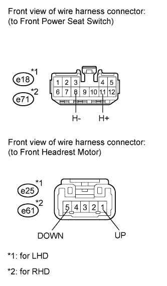
OK Measurement Condition Operational Direction Battery positive (+) → 1
Battery negative (-) → 5
Upward Battery positive (+) → 5
Battery negative (-) → 1
Downward
-
NG
REPLACE FRONT SEAT HEADREST ADJUSTER SUB-ASSEMBLY Click here
OK
-
-
CHECK HARNESS AND CONNECTOR (FRONT POWER SEAT SWITCH - FRONT HEADREST MOTOR)
-
for LHD:
-
Disconnect the e18 switch connector.
-
Disconnect the e25 motor connector.
-
-
for RHD:
-
Disconnect the e71 switch connector.
-
Disconnect the e61 motor connector.
-
-
Measure the resistance according to the value(s) in the table below.
Standard resistance for LHD Tester Connection Condition Specified Condition e18-11 (H+) - e25-1 (UP) Always Below 1 Ω e18-8 (H-) - e25-5 (DOWN) Always Below 1 Ω e18-11 (H+) - Body ground Always 10 kΩ or higher e18-8 (H-) - Body ground Always 10 kΩ or higher for RHD Tester Connection Condition Specified Condition e71-11 (H+) - e61-1 (UP) Always Below 1 Ω e71-8 (H-) - e61-5 (DOWN) Always Below 1 Ω e71-11 (H+) - Body ground Always 10 kΩ or higher e71-8 (H-) - Body ground Always 10 kΩ or higher
NG
REPAIR OR REPLACE HARNESS OR CONNECTOR
OK
REPLACE FRONT POWER SEAT SWITCH (for Passenger Side) Click here
-