INSTRUMENT PANEL SAFETY PAD INSTALLATION

Tech Tips
-
Use the same procedure for RHD and LHD vehicles.
-
The procedure listed below is for LHD vehicles.
-
A bolt without a torque specification is shown in the standard bolt chart Click here.
-
INSTALL NO. 3 INSTRUMENT PANEL STAY
-
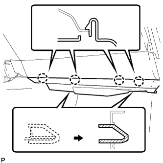
Attach the 5 claws to install the 5 No. 3 instrument panel stays.
-
-
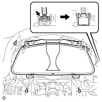
INSTALL INSTRUMENT PANEL SAFETY PAD SUB-ASSEMBLY
-
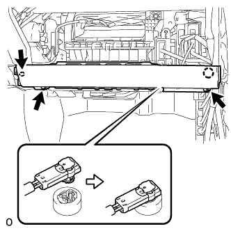
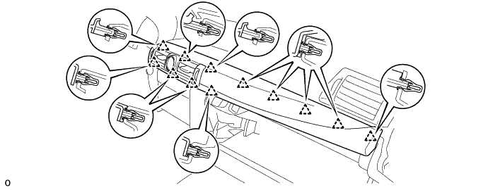
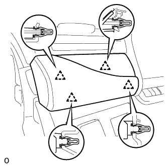
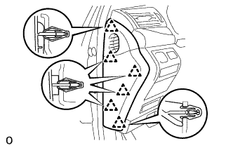
Attach the 5 clips to install the instrument panel safety pad sub-assembly.
-
Install the 2 bolts <E>.
- Torque:
- 20 N*m { 204 kgf*cm, 15 ft.*lbf }
-
Install the 8 bolts <A> and nut <F>.
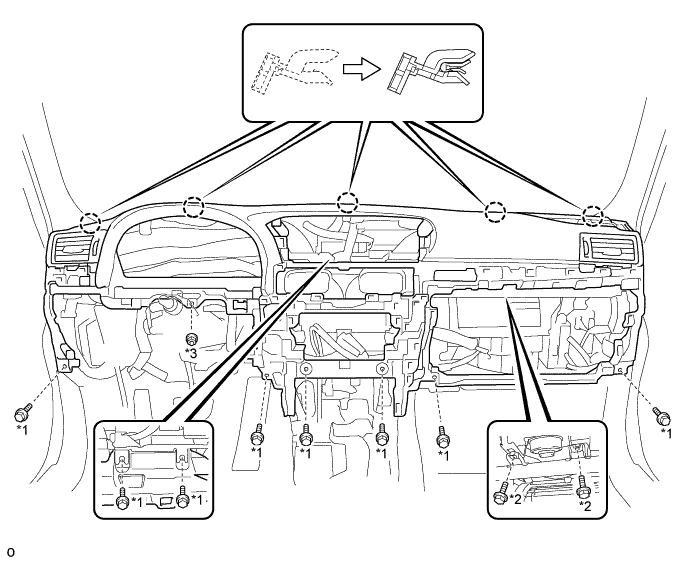
Text in Illustration *1 Bolt <A> *2 Bolt <E> *3 Nut <F> - - -
Attach the 2 claws to connect the cooler thermistor.
-
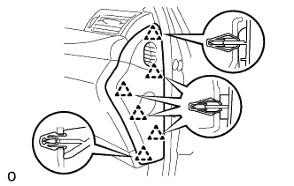
Connect each connector and attach each wire harness clamp.
-
-
INSTALL TIRE PRESSURE MONITOR RECEIVER ASSEMBLY (w/ Tire Pressure Warning System)
-
Install the tire pressure warning ECU and receiver with the bolt.
- Torque:
- for Black Bolt
- 5.5 N*m { 56 kgf*cm, 49 in.*lbf }
- for Silver Bolt
- 8.0 N*m { 82 kgf*cm, 71 in.*lbf }
Note
The torque value differs depending on whether the bolt is silver or black.
-
Connect the connector.
-
-
INSTALL TELEMATICS TRANSCEIVER (w/ G-BOOK System)
-
Connect each connector.
-
Install the telematics transceiver with the bolt and nut.
-
-
INSTALL FRONT NO. 3 SPEAKER ASSEMBLY
-
Connect the connector.
-
Temporarily install the front No. 3 speaker assembly by aligning the positioning pins of the front No. 3 speaker assembly with the instrument panel.
-
Install the front No. 3 speaker assembly with the 2 bolts.
Note
-
Do not touch the cone of the speaker.
-
When installing the speaker to the instrument panel be careful so that the wires do not get caught between the parts.
-
-
-
INSTALL NO. 1 SPEAKER HOLE COVER
-
Attach the 4 clips, claw and clamp to install the hole cover.
-
-
INSTALL FRONT NO. 2 SPEAKER ASSEMBLY (for LH Side)
-
Connect the connector.
-
Temporarily install the front No. 2 speaker assembly by aligning the positioning pins of the front No. 2 speaker assembly with the instrument panel.
-
Install the front No. 2 speaker assembly with the 2 bolts.
Note
-
Do not touch the cone of the speaker.
-
When installing the speaker to the instrument panel be careful so that the wires do not get caught between the parts.
-
-
-
INSTALL NO. 1 INSTRUMENT PANEL SPEAKER PANEL SUB-ASSEMBLY
-
Attach the 2 clips and 7 claws to install the No. 1 instrument panel speaker panel sub-assembly.
-
-
INSTALL FRONT NO. 2 SPEAKER ASSEMBLY (for RH Side)
-
Connect the connector.
-
Temporarily install the front No. 2 speaker assembly by aligning the positioning pins of the front No. 2 speaker assembly with the instrument panel.
-
Install the front No. 2 speaker assembly with the 2 bolts.
Note
-
Do not touch the cone of the speaker.
-
When installing the speaker to the instrument panel be careful so that the wires do not get caught between the parts.
-
-
-
INSTALL NO. 2 INSTRUMENT PANEL SPEAKER PANEL SUB-ASSEMBLY
-
Attach the 2 clips and 7 claws to install the No. 1 instrument panel speaker panel sub-assembly.
-
-
INSTALL FRONT PILLAR GARNISH LH
-
Attach the guide.
-
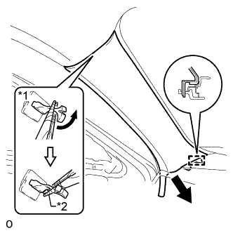
Turn the end of the front pillar garnish clip 90° with needle-nose pliers and install it to the front pillar garnish LH.
Tech Tips
Tape the tips of the needle-nose pliers before use.
Text in Illustration *1 Front Pillar Garnish Clip *2 Protective Tape -
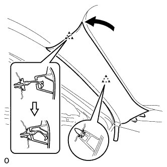
Attach the 2 clips to install the front pillar garnish LH.
Note
After installing the front pillar garnish LH, make sure that the lip of the front door opening trim weatherstrip LH is not pinched.
-
-
INSTALL FRONT PILLAR GARNISH RH
Tech Tips
Use the same procedure described for the LH side.
-
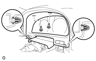
INSTALL ACCESSORY METER ASSEMBLY
-
Connect all the connectors.
-
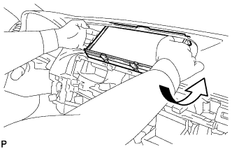
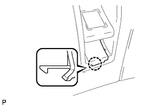
Move the accessory meter assembly in the direction of the arrow in the illustration to temporarily install it.
-
Install the accessory meter assembly with the 4 bolts.
-
-
INSTALL INSTRUMENT PANEL FINISH PANEL SUB-ASSEMBLY
-
Attach the 10 clips to install the instrument panel finish panel sub-assembly.
-
-
INSTALL GLOVE COMPARTMENT DOOR ASSEMBLY
-
Connect each connector and attach each wire harness clamp.
-
Install the glove compartment door assembly with the 5 screws <C>.
-
-
INSTALL FRONT PASSENGER SIDE KNEE AIRBAG ASSEMBLY
-
Check that the power switch is off.
-
Check that the cable is disconnected from the negative (-) auxiliary battery terminal.
CAUTION:
Wait at least 90 seconds after disconnecting the cable from the negative (-) auxiliary battery terminal to disable the SRS system.
-
Push in the lock to connect the airbag connector.
-
Connect the airbag connector to the front passenger side knee airbag assembly
Note
When connecting airbag connector, take care not to damage the airbag wire harness.
-
Attach the claw to install the front passenger side knee airbag assembly.
-
Install the 3 bolts.
- Torque:
- 10 N*m { 102 kgf*cm, 7 ft.*lbf }
Note
Confirm that the front passenger side knee airbag assembly is installed securely without any excessive gaps and is not protruding outward.
-
-
INSTALL LOWER INSTRUMENT PANEL
-
Attach the 2 claws and clip to install the lower instrument panel.
-
-
INSTALL NO. 2 INSTRUMENT PANEL UNDER COVER SUB-ASSEMBLY
-
Connect the connector.
-
Insert the 2 guides.
-
Attach the 4 claws to install the No. 2 instrument panel under cover sub-assembly.
-
-
INSTALL INSTRUMENT CLUSTER FINISH PANEL GARNISH ASSEMBLY
-
Connect each connector.
-
Attach the 12 clips to install the instrument cluster finish panel garnish assembly.
-
-
INSTALL MULTI-MEDIA MODULE RECEIVER ASSEMBLY
-
Connect the connectors.
-
Insert the multi-media module receiver assembly with bracket.
Note
When inserting the radio receiver, do not press the knobs on it.
-
Attach the 6 clips.
-
Install the multi-media module receiver assembly with bracket with the 2 bolts.
-
-
INSTALL INSTRUMENT SIDE PANEL RH
-
Attach the 6 clips to install the instrument side panel RH.
-
-
INSTALL CONSOLE BOX ASSEMBLY
-
w/o Rear Seat Entertainment System:
-
for 5-Passenger with Ottoman:
-
w/ Disc Player:
-
-
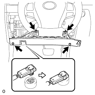
INSTALL COMBINATION METER ASSEMBLY
-
Connect the connector and attach the 2 claws to close the connector cover.
-
Install the combination meter assembly with the 4 screws.
-
-
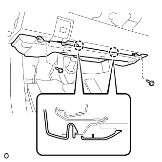
INSTALL NO. 2 INSTRUMENT CLUSTER FINISH PANEL SUB-ASSEMBLY
-
Connect the 2 connectors.
-
Attach the 2 clips to install the No. 2 instrument cluster finish panel sub-assembly.
-
Install the 2 clips.
-
-
INSTALL HEADLIGHT DIMMER SWITCH ASSEMBLY
-
INSTALL DRIVER SIDE KNEE AIRBAG ASSEMBLY
-
Check that the power switch is off.
-
Check that the cable is disconnected from the negative (-) auxiliary battery terminal.
CAUTION:
Wait at least 90 seconds after disconnecting the cable from the negative (-) auxiliary battery terminal to disable the SRS system.
-
Connect the airbag connector.
Note
When connecting airbag connector, take care not to damage the airbag wire harness.
-
Push in the lock to connect the airbag connector.
-
Attach the claw to connect the hood lock control lever sub-assembly to the driver side knee airbag assembly.
-
Attach the clip to install the driver side knee airbag assembly.
-
Install the 4 bolts.
- Torque:
- 10 N*m { 102 kgf*cm, 7 ft.*lbf }
Note
Confirm that the driver side knee airbag assembly is installed securely without any excessive gaps and is not protruding outward.
-
-
INSTALL NO. 1 INSTRUMENT PANEL UNDER COVER SUB-ASSEMBLY
-
Connect each connector and attach each wire harness clamp.
-
Attach the 2 claws to connect the DLC3.
-
Attach the 2 claws to install the No. 1 instrument panel under cover sub-assembly.
-
Install the 2 screws.
-
-
INSTALL NO. 1 INSTRUMENT PANEL SAFETY PAD SUB-ASSEMBLY
-
Connect each connector.
-
Attach the 5 clips and claw to install the No. 1 instrument panel safety pad sub-assembly.
-
Install the screw <C> and bolt.
-
Attach the claw to install the switch base hole cover to the No. 1 instrument panel safety pad sub-assembly.
-
-
INSTALL INSTRUMENT PANEL ORNAMENT
-
Connect the connector.
-
Attach the 4 clips to install the instrument panel ornament.
-
-
INSTALL INSTRUMENT SIDE PANEL LH
-
Attach the 6 clips to install the instrument side panel LH.
-
-
CONNECT CABLE TO AUXILIARY BATTERY NEGATIVE TERMINAL
Note
When disconnecting the cable, some systems need to be initialized after the cable is reconnected Click here.
-
ENABLE AUTOAWAY/RETURN FUNCTION
-
Restore the autoaway/return function setting to the previous condition by changing the customize parameter Click here.
-
-
INSTALL BATTERY SERVICE HOLE COVER LH
-

Text in Illustration *A for Standard *B for Ottoman Attach the battery service hole cover LH with the clip and fastening tape.
-
-
INSTALL DECK TRIM SIDE BOARD LH (w/o Spare Tire)
-

Attach the 2 clips to install the deck trim side board LH.
-
-
INSTALL DECK BOARD ASSEMBLY (w/o Spare Tire)

-
INSTALL LUGGAGE COMPARTMENT MAT SUB-ASSEMBLY (w/ Spare Tire)

-
CHECK SRS WARNING LIGHT