INSTRUMENT PANEL SAFETY PAD REASSEMBLY

Tech Tips
-
Use the same procedure for RHD and LHD vehicles.
-
The procedure listed below is for LHD vehicles.
-
A bolt without a torque specification is shown in the standard bolt chart Click here.
-
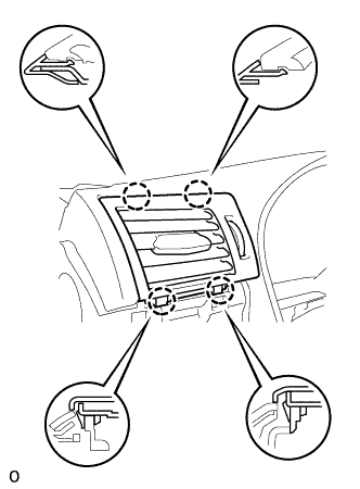
INSTALL NO. 1 INSTRUMENT PANEL REGISTER ASSEMBLY
-
Attach the 4 claws to install the No. 1 instrument panel register assembly.
-
-
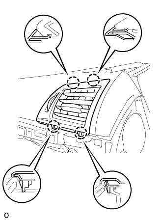
INSTALL NO. 2 INSTRUMENT PANEL REGISTER ASSEMBLY
-
Attach the 4 claws to install the No. 2 instrument panel register assembly.
-
-
INSTALL NO. 1 METER HOOD RETAINER
-
Install the 2 No. 1 meter hood retainers with the 2 screws.
-
-
INSTALL NO. 1 INSTRUMENT PANEL PIN
Tech Tips
Use the same procedure to install the No. 1 instrument panel pin on the other side.
-
Install the No. 1 instrument panel pin with the screw.
-
-
INSTALL NO. 2 INSTRUMENT PANEL WIRE
-
Attach the 5 wire harness clamps to install the No. 2 instrument panel wire.
-
-
INSTALL AUTOMATIC LIGHT CONTROL SENSOR
-
Attach the 2 claws to install the automatic light control sensor.
-
Connect the connector.
-
-
INSTALL NAVIGATION ANTENNA ASSEMBLY
-
Attach the 4 clamps.
-
Install the navigation antenna assembly with the 2 screws.
-
-
INSTALL FRONT PASSENGER AIRBAG ASSEMBLY
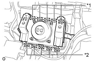
Text in Illustration *1 Hook (A) *2 Hook (B)
-
Attach the 5 hooks (A).
-
Push the front passenger airbag assembly to attach the 5 hooks (B).
-
Install the 2 screws.
-
-
INSTALL NO. 2 INSTRUMENT PANEL WIRE
-
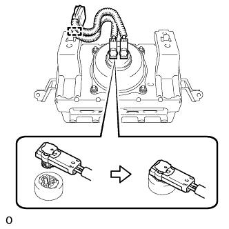
Connect the 2 airbag connectors.
Note
-
When connecting airbag connector, take care not to damage the airbag wire harness.
-
Be sure to only connect the connectors to each corresponding color.
-
-
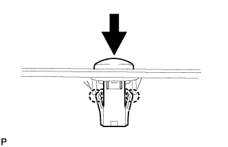
Push in the lock to connect the airbag connector.
-
Attach the clamp to install the No. 2 instrument panel wire to the front passenger airbag assembly.
-
-
INSTALL ION GENERATOR SUB-ASSEMBLY
-
Install the ion generator sub-assembly with the 2 screws.
-
Connect the connector and heater to register duct.
-
-
INSTALL NO. 2 HEATER TO REGISTER DUCT
-
Install the No. 2 heater to register duct with the 2 screws.
-
Connect the hose to the ion generator sub-assembly.
-
-
INSTALL DEFROSTER NOZZLE ASSEMBLY
-
Install the defroster nozzle assembly with the 3 screws.
-
-
INSTALL NO. 3 HEATER TO REGISTER DUCT
-
Install the No. 3 heater to register duct with the 3 screws.
-
-
INSTALL NO. 1 HEATER TO REGISTER DUCT
-
Install the No. 1 heater to register duct with the 3 screws.
-
-
INSTALL NO. 2 SIDE DEFROSTER NOZZLE DUCT
-
Attach the claw to install the No. 2 side defroster nozzle duct.
-
Install the screw.
-
-
INSTALL NO. 1 SIDE DEFROSTER NOZZLE DUCT
-
Attach the claw to install the No. 1 side defroster nozzle duct.
-
Install the screw.
-
-
INSTALL NO. 1 COMBINATION METER BRACKET
-
Install the No. 1 combination meter bracket.
-