INSTRUMENT PANEL SAFETY PAD DISASSEMBLY

Tech Tips
-
Use the same procedure for RHD and LHD vehicles.
-
The procedure listed below is for LHD vehicles.
-
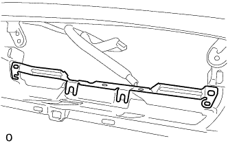
REMOVE NO. 1 COMBINATION METER BRACKET
-
Remove the No. 1 combination meter bracket.
-
-
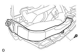
REMOVE NO. 1 SIDE DEFROSTER NOZZLE DUCT
-
Remove the screw.
-
Detach the claw and remove the No. 1 side defroster nozzle duct.
-
-
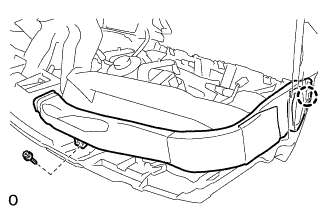
REMOVE NO. 2 SIDE DEFROSTER NOZZLE DUCT
-
Remove the screw.
-
Detach the claw and remove the No. 2 side defroster nozzle duct.
-
-
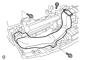
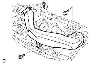
REMOVE NO. 1 HEATER TO REGISTER DUCT
-
Remove the 3 screws and No. 1 heater to register duct.
-
-
REMOVE NO. 3 HEATER TO REGISTER DUCT
-
Remove the 3 screws and No. 3 heater to register duct.
-
-
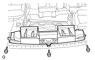
REMOVE DEFROSTER NOZZLE ASSEMBLY
-
Remove the 3 screws and defroster nozzle assembly.
-
-
REMOVE NO. 2 HEATER TO REGISTER DUCT
-
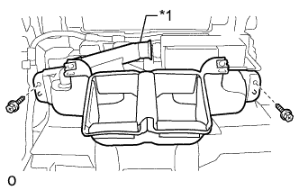
Text in Illustration *1 Hose Disconnect the hose from the ion generator sub-assembly.
-
Remove the 2 screws and No. 2 heater to register duct.
-
-
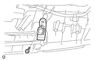
REMOVE ION GENERATOR SUB-ASSEMBLY
-
Disconnect the connector and heater to register duct.
-
Remove the 2 screws and ion generator sub-assembly.
-
-
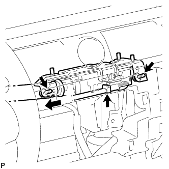
REMOVE NO. 2 INSTRUMENT PANEL WIRE
-
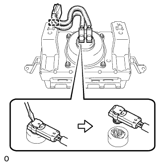
Detach the connector clamp.
-
Using a screwdriver release the airbag connector lock.
-
Using a screwdriver, disconnect the 2 airbag connectors to remove the No. 2 instrument panel wire from the front passenger airbag assembly.
Note
When disconnecting airbag connector, take care not to damage the airbag wire harness.
-
-
REMOVE FRONT PASSENGER AIRBAG ASSEMBLY
CAUTION:
When storing the front passenger airbag assembly, keep the airbag deployment side facing upward.
-
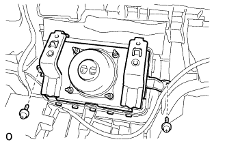
Remove the 2 screws.
-
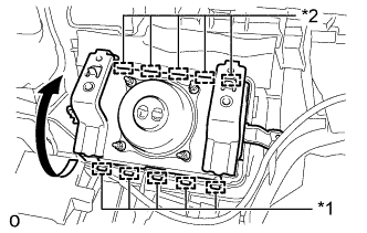
Text in Illustration *1 Hook (A) *2 Hook (B) Detach the 5 hooks (A).
-
Detach the 5 hooks (B) to remove the front passenger airbag assembly from the instrument panel safety pad assembly as shown in the illustration.
-
-
REMOVE NAVIGATION ANTENNA ASSEMBLY
-
Detach the 4 clamps.
-
Remove the 2 screws and navigation antenna assembly.
-
-
REMOVE AUTOMATIC LIGHT CONTROL SENSOR
-
Disconnect the connector.
-
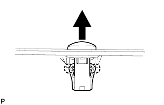
Detach the 2 claws and remove the automatic light control sensor.
-
-
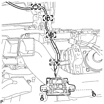
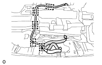
REMOVE NO. 2 INSTRUMENT PANEL WIRE
-
Detach the 5 wire harness clamps and remove the No. 2 instrument panel wire.
-
-
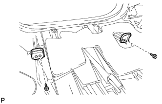
REMOVE NO. 1 INSTRUMENT PANEL PIN
Tech Tips
Use the same procedure to remove the No. 1 instrument panel pin on the other side.
-
Remove the screw and No. 1 instrument panel pin.
-
-
REMOVE NO. 1 METER HOOD RETAINER
-
Remove the 2 screws and 2 No. 1 meter hood retainers.
-
-
REMOVE NO. 1 INSTRUMENT PANEL REGISTER ASSEMBLY
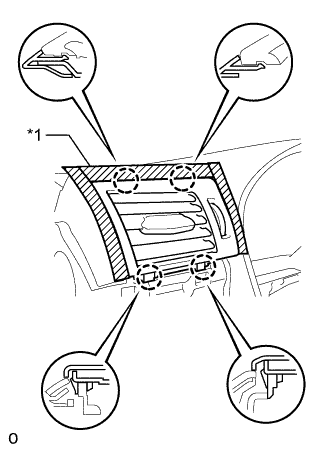
Text in Illustration *1 Protective Tape
-
Apply protective tape as shown in the illustration.
-
Detach the 4 claws and remove the No. 1 instrument panel register assembly.
-
-
REMOVE NO. 2 INSTRUMENT PANEL REGISTER ASSEMBLY
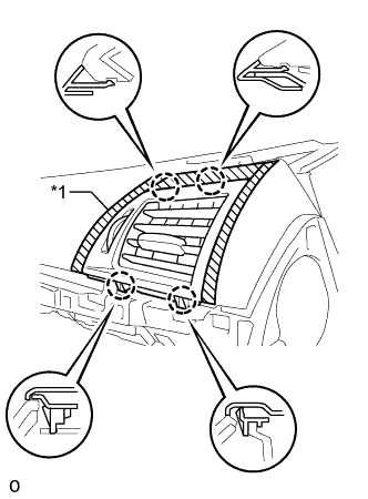
Text in Illustration *1 Protective Tape
-
Apply protective tape as shown in the illustration.
-
Detach the 4 claws and remove the No. 2 instrument panel register assembly.
-