FRONT POWER SEAT CONTROL SYSTEM, Diagnostic DTC:B265B

| DTC Code | DTC Name |
|---|---|
| B265B | Lumbar Support Sensor Circuit |
DESCRIPTION
When the front power seat switch (seat ECU) does not receive a sensor signal despite forward or backward movement of the seat by power seat motor operation, this DTC is stored.
| DTC Code | DTC Detection Condition | Trouble Area |
|---|---|---|
| B265B | The forward and backward lock detection position of the sensor is the same. |
|
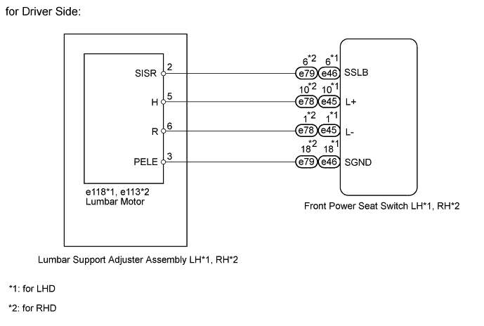
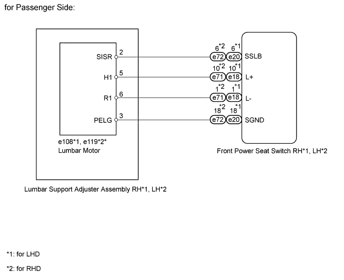
WIRING DIAGRAM
INSPECTION PROCEDURE
PROCEDURE
-
CHECK FOR DTC
-
DTC output area check
-
Using the intelligent tester, determine the area that output the DTC.
Result Result Proceed to B265B output from driver seat ECU A B265B output from passenger seat ECU B
-
B 
PERFORM ACTIVE TEST USING INTELLIGENT TESTER (LUMBAR SLIDE) Click here
A 
-
-
PERFORM ACTIVE TEST USING INTELLIGENT TESTER (POWER SEAT MOTOR FUNCTION)
-
Select the Active Test, use the intelligent tester to generate a control command, and then check the power seat motor function.
Driver Seat Tester Display Test Part Control Range Diagnostic Note Lumbar Slide Lumbar sliding operation Front / OFF / Rear - OK Motor operates normally.
NG
CHECK LUMBAR SUPPORT ADJUSTER ASSEMBLY (POWER SEAT MOTOR) Click here
OK
-
-
CHECK FRONT POWER SEAT SWITCH (POSITION CONTROL SENSOR)
-
for LHD:
-
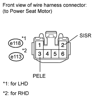
Disconnect the e118 motor connector.
-
-
for RHD:
-
Disconnect the e113 motor connector.
-
-
Measure the voltage according to the value(s) in the table below.
Standard voltage for LHD Tester Connection Switch Condition Specified Condition e118-2 (SISR) - e118-3 (PELE) Lumbar switch ON 4.8 to 5.1 V for RHD Tester Connection Switch Condition Specified Condition e113-2 (SISR) - e113-3 (PELE) Lumbar switch ON 4.8 to 5.1 V
NG
CHECK HARNESS AND CONNECTOR (FRONT POWER SEAT SWITCH - POWER SEAT MOTOR) Click here
OK
-
-
CHECK LUMBAR SUPPORT ADJUSTER ASSEMBLY LH (POSITION CONTROL SENSOR)
-
Measure the voltage according to the value(s) in the table below.
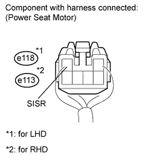
Standard voltage for LHD Tester Connection Switch Condition Specified Condition e118-2 (SISR) - Body ground Lumbar switch ON 4.5 to 4.8 V for RHD Tester Connection Switch Condition Specified Condition e113-2 (SISR) - Body ground Lumbar switch ON 4.5 to 4.8 V
NG 
REPLACE LUMBAR SUPPORT ADJUSTER ASSEMBLY (LUMBAR MOTOR) Click here
OK 
REPLACE FRONT POWER SEAT SWITCH Click here
-
-
CHECK HARNESS AND CONNECTOR (FRONT POWER SEAT SWITCH - POWER SEAT MOTOR)
-
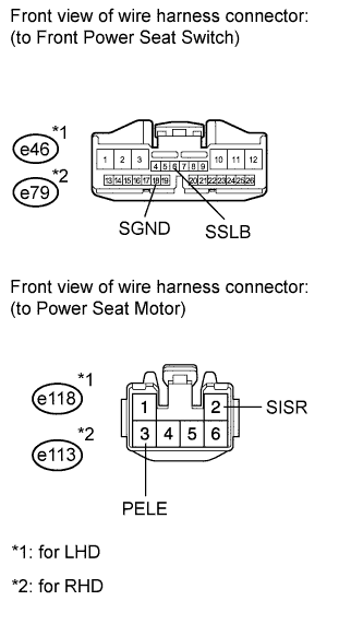
for LHD:
-
Disconnect the e46 switch connector.
-
Disconnect the e118 motor connector.
-
-
for RHD:
-
Disconnect the e79 switch connector.
-
Disconnect the e113 motor connector.
-
-
Measure the resistance according to the value(s) in the table below.
Standard resistance for LHD Tester Connection Condition Specified Condition e46-6 (SSLB) - e118-2 (SISR) Always Below 1 Ω e46-18 (SGND) - e118-3 (PELE) Always Below 1 Ω e46-6 (SSLB) - Body ground Always 10 kΩ or higher e46-18 (SGND) - Body ground Always 10 kΩ or higher for RHD Tester Connection Condition Specified Condition e79-6 (SSLB) - e113-2 (SISR) Always Below 1 Ω e79-18 (SGND) - e113-3 (PELE) Always Below 1 Ω e79-6 (SSLB) - Body ground Always 10 kΩ or higher e79-18 (SGND) - Body ground Always 10 kΩ or higher
NG
REPAIR OR REPLACE HARNESS OR CONNECTOR
OK
REPLACE FRONT POWER SEAT SWITCH Click here
-
-
CHECK LUMBAR SUPPORT ADJUSTER ASSEMBLY (POWER SEAT MOTOR)
-
Remove the lumbar support adjuster assembly Click here.
-
Inspect the lumbar support adjuster assembly Click here.
NG
REPLACE LUMBAR SUPPORT ADJUSTER ASSEMBLY Click here
OK
-
-
CHECK HARNESS AND CONNECTOR (FRONT POWER SEAT SWITCH - POWER SEAT MOTOR)
-
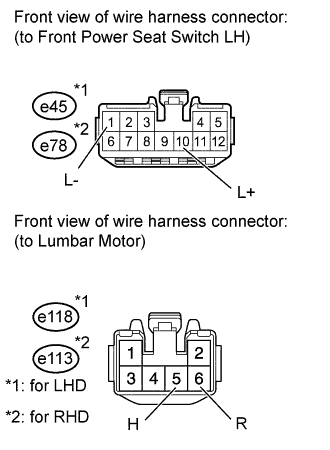
for LHD:
-
Disconnect the e45 switch connector.
-
Disconnect the e118 motor connector.
-
-
for RHD:
-
Disconnect the e78 switch connector.
-
Disconnect the e113 motor connector.
-
-
Measure the resistance according to the value(s) in the table below.
Standard resistance for LHD Tester Connection Condition Specified Condition e45-10 (L+) - e118-5 (H) Always Below 1 Ω e45-1 (L-) - e118-6 (R) Always Below 1 Ω e45-10 (L+) - Body ground Always 10 kΩ or higher e45-1 (L-) - Body ground Always 10 kΩ or higher for RHD Tester Connection Condition Specified Condition e78-10 (L+) - e113-5 (H) Always Below 1 Ω e78-1 (L-) - e113-6 (R) Always Below 1 Ω e78-10 (L+) - Body ground Always 10 kΩ or higher e78-1 (L-) - Body ground Always 10 kΩ or higher
NG
REPAIR OR REPLACE HARNESS OR CONNECTOR
OK
REPLACE FRONT POWER SEAT SWITCH Click here
-
-
PERFORM ACTIVE TEST USING INTELLIGENT TESTER (LUMBAR SLIDE)
-
Select the Active Test, use the intelligent tester to generate a control command, and then check the power seat motor function.
Passenger Seat Tester Display Test Part Control Range Diagnostic Note Lumbar Slide Lumbar sliding operation Front / OFF / Rear - OK Motor operates normally.
NG
CHECK LUMBAR SUPPORT ADJUSTER ASSEMBLY (POWER SEAT MOTOR) Click here
OK
-
-
CHECK FRONT POWER SEAT SWITCH (LUMBAR MOTOR CIRCUIT)
-
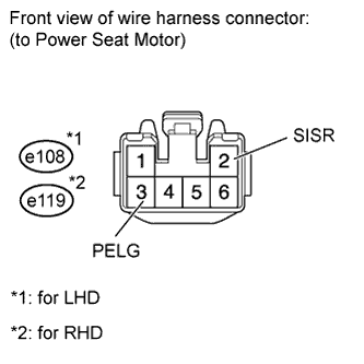
for LHD:
-
Disconnect the e108 motor connector.
-
-
for RHD:
-
Disconnect the e119 motor connector.
-
-
Measure the voltage according to the value(s) in the table below.
Standard voltage for LHD Tester Connection Switch Condition Specified Condition e108-2 (SISR) - e108-3 (PELG) Lumbar switch ON 4.8 to 5.1 V for RHD Tester Connection Switch Condition Specified Condition e119-2 (SISR) - e119-3 (PELG) Lumbar switch ON 4.8 to 5.1 V
NG
CHECK HARNESS AND CONNECTOR (FRONT POWER SEAT SWITCH - LUMBAR SUPPORT ADJUSTER ASSEMBLY RH) Click here
OK
-
-
CHECK LUMBAR SUPPORT ADJUSTER ASSEMBLY RH (LUMBAR MOTOR)
-
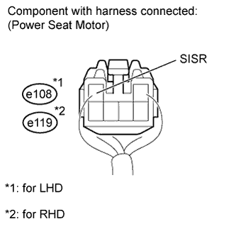
Measure the voltage according to the value(s) in the table below.
Standard voltage for LHD Tester Connection Switch Condition Specified Condition e108-2 (SISR) - Body ground Lumbar switch ON 4.5 to 4.8 V for RHD Tester Connection Switch Condition Specified Condition e119-2 (SISR) - Body ground Lumbar switch ON 4.5 to 4.8 V
NG
REPLACE LUMBAR SUPPORT ADJUSTER ASSEMBLY Click here
OK
REPLACE FRONT POWER SEAT SWITCH Click here
-
-
CHECK HARNESS AND CONNECTOR (FRONT POWER SEAT SWITCH - LUMBAR SUPPORT ADJUSTER ASSEMBLY RH)
-
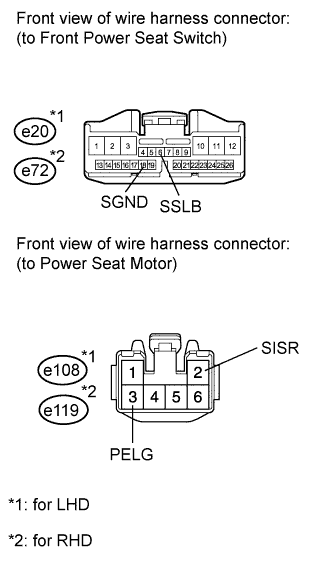
for LHD:
-
Disconnect the e20 switch connector.
-
Disconnect the e108 motor connector.
-
-
for RHD:
-
Disconnect the e72 switch connector.
-
Disconnect the e119 motor connector.
-
-
Measure the resistance according to the value(s) in the table below.
Standard resistance for LHD Tester Connection Condition Specified Condition e20-6 (SSLB) - e108-2 (SISR) Always Below 1 Ω e20-18 (SGND) - e108-3 (PELG) Always Below 1 Ω e20-6 (SSLB) - Body ground Always 10 kΩ or higher e20-18 (SGND) - Body ground Always 10 kΩ or higher for RHD Tester Connection Condition Specified Condition e72-6 (SSLB) - e119-2 (SISR) Always Below 1 Ω e72-18 (SGND) - e119-3 (PELG) Always Below 1 Ω e72-6 (SSLB) - Body ground Always 10 kΩ or higher e72-18 (SGND) - Body ground Always 10 kΩ or higher
NG
REPAIR OR REPLACE HARNESS OR CONNECTOR
OK
REPLACE FRONT POWER SEAT SWITCH Click here
-
-
CHECK LUMBAR SUPPORT ADJUSTER ASSEMBLY (POWER SEAT MOTOR)
-
Remove the lumbar support adjuster assembly RH Click here.
-
Inspect the lumbar support adjuster assembly RH Click here.
NG
REPLACE LUMBAR SUPPORT ADJUSTER ASSEMBLY Click here
OK
-
-
CHECK HARNESS AND CONNECTOR (FRONT POWER SEAT SWITCH - POWER SEAT MOTOR)
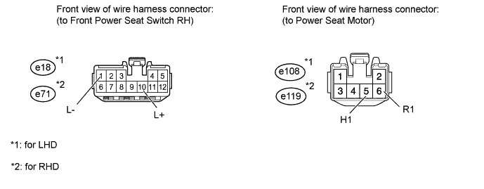
-
for LHD:
-
Disconnect the e20 switch connector.
-
Disconnect the e108 motor connector.
-
-
for RHD:
-
Disconnect the e71 switch connector.
-
Disconnect the e119 motor connector.
-
-
Measure the resistance according to the value(s) in the table below.
Standard resistance for LHD Tester Connection Condition Specified Condition e18-10 (L+) - e108-5 (H1) Always Below 1 Ω e18-1 (L-) - e108-6 (R1) Always Below 1 Ω e18-10 (L+) - Body ground Always 10 kΩ or higher e18-1 (L-) - Body ground Always 10 kΩ or higher for RHD Tester Connection Condition Specified Condition e71-10 (L+) - e119-5 (H1) Always Below 1 Ω e71-1 (L-) - e119-6 (R1) Always Below 1 Ω e71-10 (L+) - Body ground Always 10 kΩ or higher e71-1 (L-) - Body ground Always 10 kΩ or higher
NG
REPAIR OR REPLACE HARNESS OR CONNECTOR
OK
REPLACE FRONT POWER SEAT SWITCH Click here
-