INNER REAR VIEW MIRROR REMOVAL

Tech Tips
-
Use the same procedure for RHD and LHD vehicles.
-
The procedure listed below is for LHD vehicles.
-
PRECAUTION
Note
After turning the power switch off, waiting time may be required before disconnecting the cable from the auxiliary battery terminal. Therefore, make sure to read the disconnecting the cable from the auxiliary battery terminal notice before proceeding with work Click here.
-
REMOVE LUGGAGE COMPARTMENT MAT SUB-ASSEMBLY (w/ Spare Tire)

-
REMOVE DECK BOARD ASSEMBLY (w/o Spare Tire)

-
REMOVE DECK TRIM SIDE BOARD LH (w/o Spare Tire)
-

Detach the 2 clips and remove the deck trim side board LH.
-
-
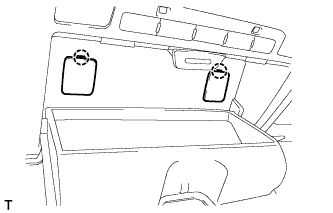
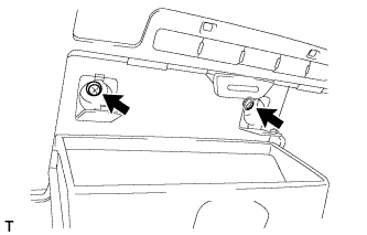
REMOVE BATTERY SERVICE HOLE COVER LH
-

Text in Illustration *A for Standard *B for Ottoman *1 Fastening Tape Detach the clip, fastening tape and remove the battery service hole cover LH.
-
-
DISCONNECT CABLE FROM AUXILIARY BATTERY NEGATIVE TERMINAL
Note
When disconnecting the cable, some systems need to be initialized after the cable is reconnected Click here.
-
REMOVE MAP LIGHT ASSEMBLY
-
Using a screwdriver, detach the 2 claws and 2 covers.
Tech Tips
Tape the screwdriver tip before use.
-
Remove the 2 screws.
-
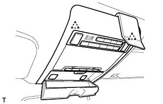
Using a moulding remover, detach the 2 clips.
-
Disconnect the connectors and remove the map light assembly.
-
-
REMOVE RAIN SENSOR COVER (w/o Lane Keeping Assist System)
-
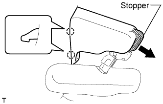
Pull the stopper in the direction shown in the illustration.
-
Detach the 2 claws and remove the rain sensor cover.
-
-
REMOVE RAIN SENSOR COVER (w/ Lane Keeping Assist System)
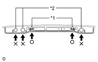
Text in Illustration *1 Clip *2 Camera Note
When removing the rain sensor cover, do not apply force to the object recognition camera areas labeled "X".
-
Pull the stopper in the direction shown in the illustration.
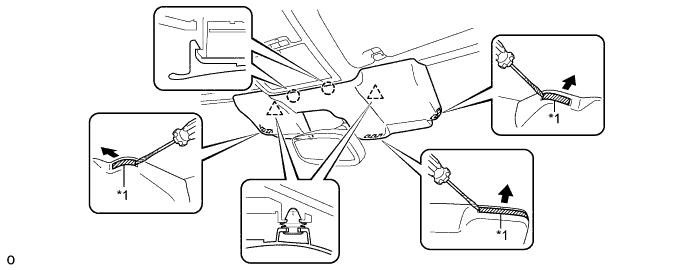
Text in Illustration *1 Stopper - - -
While being careful not to apply force to the camera areas, detach the 2 clips and 2 claws and remove the rain sensor cover.
-
-
REMOVE INNER REAR VIEW MIRROR ASSEMBLY (w/o Automatic High Beam System, Adaptive High Beam System)
-
Disconnect the connector.
-
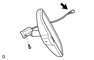
Using a T20 "TORX" socket wrench, remove the screw and inner rear view mirror.
-
-
REMOVE INNER REAR VIEW MIRROR ASSEMBLY (w/ Automatic High Beam System, Adaptive High Beam System)
Note
-
Do not touch the camera lens (built into the inner rear view mirror assembly) with a bare hand.
-
Do not allow anything to adhere to the camera lens (built into the inner rear view mirror assembly).
-
Do not apply strong impacts to the inner rear view mirror assembly.
-
Do not allow any liquids to get on the inner rear view mirror assembly.
-
Disconnect the connector.
-
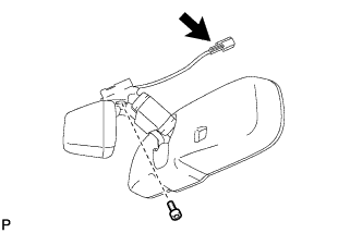
Using a T20 "TORX" socket wrench, remove the screw and inner rear view mirror.
-